Mitsubishi Outlander (2013+). Manual - part 394
AC102513
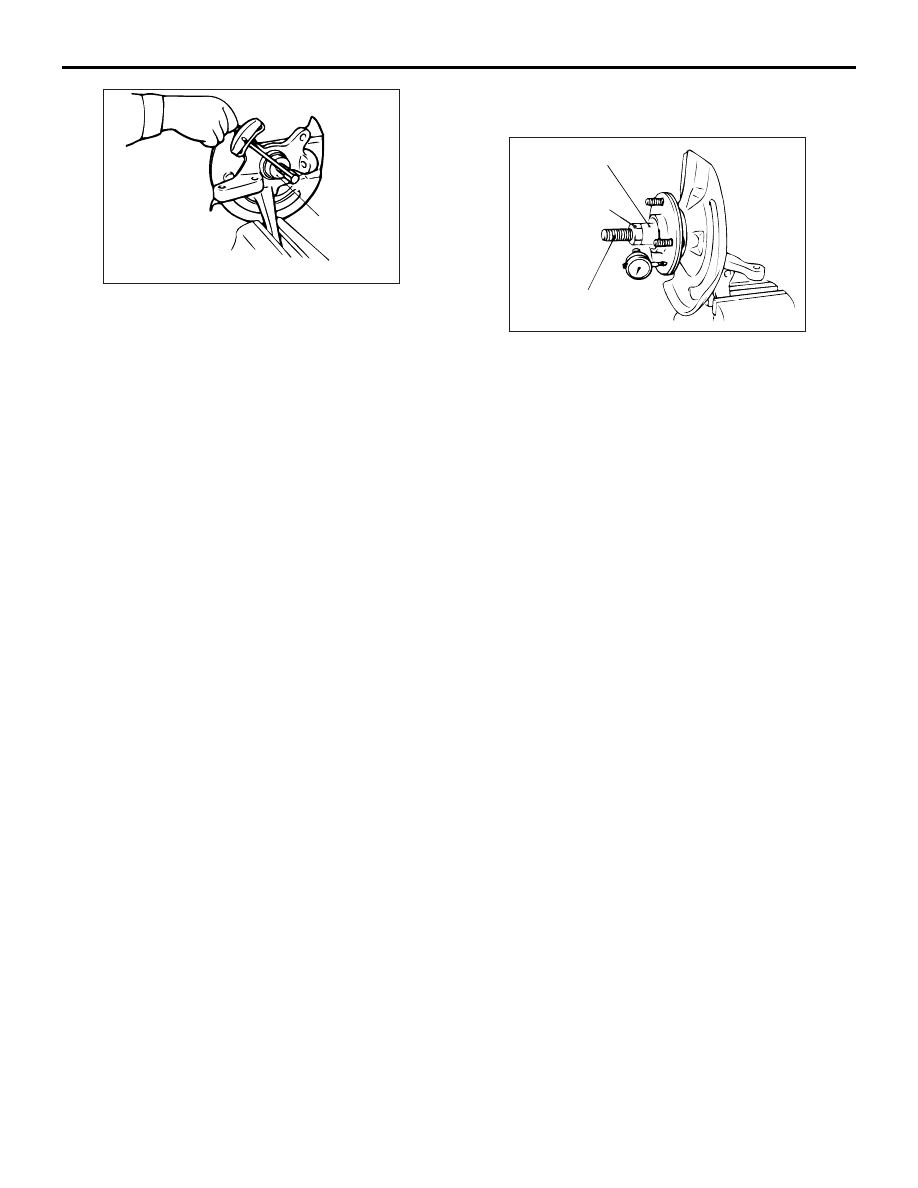
MB990326
AB
FRONT AXLE HUB ASSEMBLY
FRONT AXLE
26-14
3. Use special tool preload socket (MB990326) to
measure the hub rotation starting torque.
Limit: 1.5 N
⋅m
4. Hub rotation starting torque should be within the
limit value, and there should be no roughness and
gritty feeling in rotation.
>>D<< WHEEL BEARING AXIAL PLAY
CHECK
AC102514 AN
MB991017
MB991000
270 ± 27 N·m
Tighten the nut with
the bolt secured.
1. Use the following special tools to measure the
wheel bearing axial play:
• Spacer (MB991000)
• Front hub remover and installer (MB991017)
Limit: 0.05 mm
2. If the axial play is not within the limit range while
the nut is tightened to the specified torque, the
bearing, hub and/or knuckle have probably not
been installed correctly. Replace the bearing and
re-install.
Tightening torque: 270
± 27 N⋅m