Mitsubishi Outlander (2013+). Manual - part 393


  Index      Mitsubishi     Mitsubishi Outlander - service repair manual 2013 year


Search            


Content   ..  391  392  393  394   ..


Mitsubishi Outlander (2013+). Manual - part 393


FRONT AXLE HUB ASSEMBLY

FRONT AXLE

26-10

INSTALLATION SERVICE POINTS

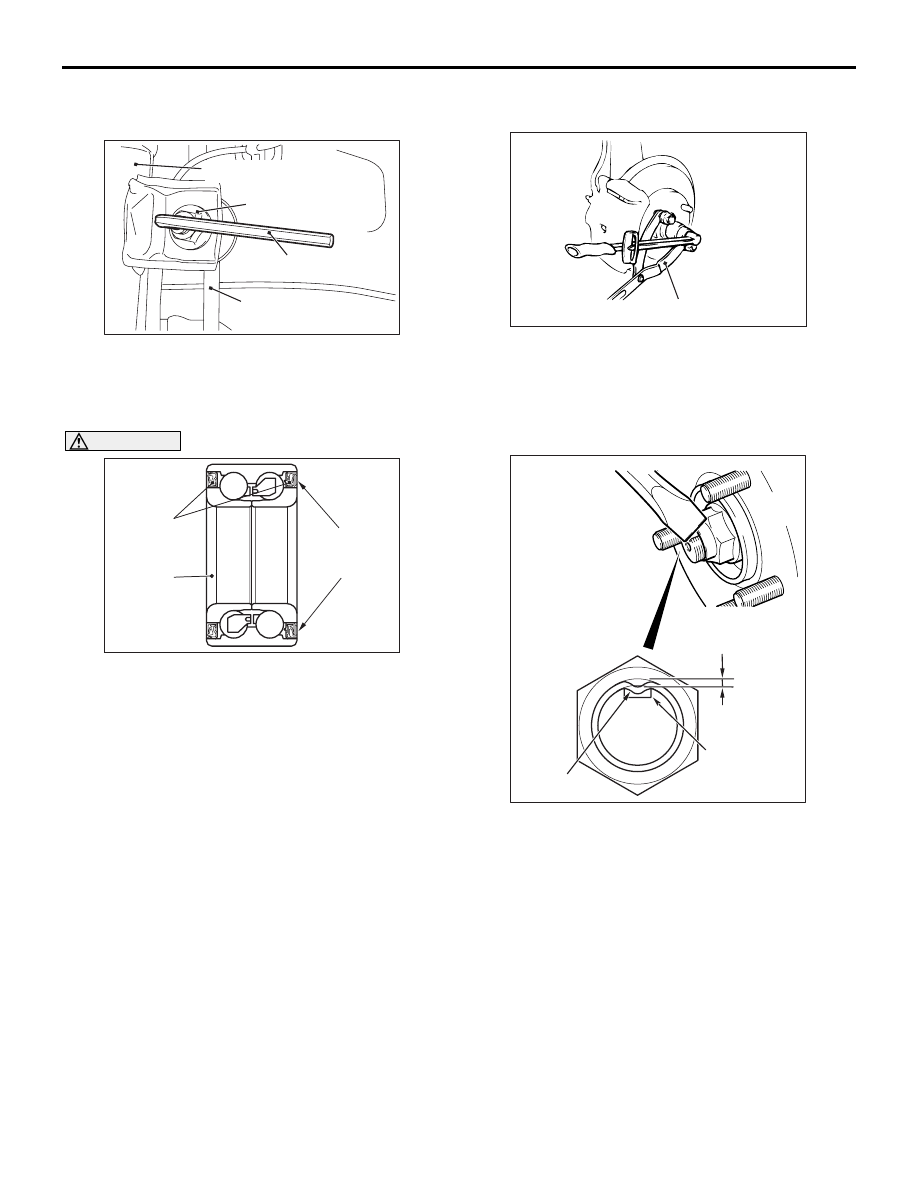
>>A<< STABILIZER LINK CONNECTION

AC613526 AB

Stabilizer link

Strut assembly

Hexagon wrench

Stabilizer link and
strut connection nut

Use a hexagon wrench to install the stabilizer link 
and strut connection nut as shown in the figure.

>>B<< DRIVESHAFT NUT INSTALLATION

CAUTION

AC504925

Oil seal

Magnetic
encoder

AC

Wheel
bearing

The magnetic encoder collects metallic particles 

easily, because it is magnetized. Make sure 
that the magnetic encoder should not collect 
metallic particles. Check that there is not any 
trouble prior to reassembling it.

• When installing the driveshaft, make sure that 

it does not contact with the magnetic encoder 
(integrated with the inner oil seal) to avoid 
damage.

• Do not apply the vehicle weight on the wheel 

bearing before fully tightening the driveshaft 
nut. Otherwise, the wheel bearing may be bro-
ken.

• Insert the driveshaft so that no hub bolt is ver-

tically above the groove of the driveshaft 
assembly.

1. Check the hub seated surface for damage or 

corrosion. Whenever solvent is used for removing 
the corrosion, the surface should be degreased.

2. Check that the new driveshaft nut can be turned 

smoothly by hand. Then tighten it until it is seated.

ACB04979AB

MB990767

3. Using special tool front hub and flange yoke 

holder (MB990767), tighten the driveshaft nut.

Tightening torque: 270 

± 27 Nm

4. After tightening to the specified torque, check that 

the nut is seated securely.

ACA01211

1.6 mm 
or more

AC

Groove

Staked portion

5. Use the chisel and a hammer to stake the nut until 

the centre in the staked portion reaches the 
shown dimension.

6. Finally, check that the nut is not cracked at its 

staked portion.

FRONT AXLE HUB ASSEMBLY

FRONT AXLE

26-11

DISASSEMBLY AND REASSEMBLY

M1261001900993

AC505536

N

4

1

5

N

3

2

AB

Disassembly steps 

<<

A

>>

1.

Hub

2.

Dust shield

3.

Snap ring

<<

B

>>

4.

Wheel bearing

5.

Knuckle
Reassembly steps 

5.

Knuckle

>>

A

<<

4.

Wheel bearing

3.

Snap ring

>>

B

<<

2.

Dust shield

1.

Hub

>>

C

<<

Hub rotation starting torque check

>>

D

<<

Wheel bearing axial play check

DISASSEMBLY SERVICE POINTS

<<A>> HUB REMOVAL

CAUTION

In the hub removal operation, make sure to 
replace the wheel bearing with new one.

AC709343

Guide

MB991355

MB992250

MB991355

AB

1. Replace special tool Knuckle arm bridge 

attachment (MB992250) with a guide of special 
tool Knuckle arm bridge (MB991355) as shown in 
the figure.

AC709110AB

Spacers

MB992250

Knuckle

FRONT AXLE HUB ASSEMBLY

FRONT AXLE

26-12

2. Insert special tool MB992250 in the knuckle and 

tighten it with a bolt and nut.

NOTE: Set the spacers of special tool MB992250 
as shown in the figure.

AC702984

AC709106

Tighten the nut
with the bolt 
secured

MB991355

MB991017

MB991000

AB

MB992250

3. Use the following special tools to remove the hub:

• Spacer (MB991000)

• Front hub remover and installer (MB991017)

• Knuckle arm bridge (MB991355)

• Knuckle arm bridge attachment (MB992250)

<<B>> WHEEL BEARING REMOVAL

AC611145 AD

MB991000

MD998801

Inner race

Hub

1. Use the following special tools to remove the 

wheel bearing inner race (outside) from the hub.

• Spacer (MB991000)

AC611146 AD

MD998812

MB992150

MD998813

Inner race
(outside)

Remover (MD998801)

2. Use the following special tools to assemble the 

inner race (outside) removed from the hub to the 
wheel bearing.

• Oil seal installer (MB992150)

• Installer cap (MD998812)

AC507657

MB990938

MB990935

AD

Installer (MD998813)

3. Use the following special tools to remove the 

wheel bearing.

• Installer adapter (MB990935)

• Installer bar (MB990938)

FRONT AXLE HUB ASSEMBLY

FRONT AXLE

26-13

REASSEMBLY SERVICE POINTS

>>A<< WHEEL BEARING INSTALLATION

CAUTION

AC209054

AC505560AC

Knuckle

Driveshaft

Hub

Oil seal
(Silver)

Encoder
(Dark brown)

The magnetic encoder for wheel speed sensor is 

installed in the wheel bearing. Install the 
wheel bearing so that the encoder is posi-
tioned in the direction shown in the figure.

• When press-fit the wheel bearing, push the 

outer race.

• After press-fit the wheel bearing, wipe off the 

extra grease in order not to remain on the 
magnetic encoder.

1. Remove grease and foreign material cleanly from 

the inside of knuckle bore.

AC611147AF

MB990890

MD999528

2. Apply the specified grease thinly and evenly to the 

inside of knuckle as shown in the figure.

Specified grease: Shell Sunlight Grease BD2 
or equivalent

Amount to use: as required (1.0 

 1.5 g)

3. Use the following special tools to press-fit the 

wheel bearing:

• Rear suspension bushing base (MB990890)

• Adapter (MD999528)

4. Remove excessive grease seeped out between 

knuckle and wheel bearing outer race after 
press-fitting the wheel bearing.

>>B<< DUST SHIELD INSTALLATION

AC602563 AC

Bolt

Dust shield

MB991388

MB991576

Use the following special tools to press-fit the 
knuckle into the dust shield.

• Bush remover base (MB991388)

• Base (MB991576)

NOTE: Use the bolts (M12) to align the caliper 
mounting holes.

>>C<< HUB ROTATION STARTING 
TORQUE CHECK

AC210315

AC505562

AC611153 AI

MB991017

MB991099

MB991000

270 

±

 27 N·m

Tighten the nut with 
the bolt secured

1. Set the following special tools as shown in the 

figure, tighten the nut to the specified torque, and 
press-fit the hub into the knuckle:

• Spacer (MB991000)

• Front hub remover and installer (MB991017)

• Oil seal installer guide (MB991099)

2. Rotate the hub to make the bearing well-greased.


Content   ..  391  392  393  394   ..