Mitsubishi Outlander (2013+). Manual - part 276
 

  Index      Mitsubishi     Mitsubishi Outlander - service repair manual 2013 year


Search            


Content   ..  274  275  276  277   ..


Mitsubishi Outlander (2013+). Manual - part 276


AK502749

90˚

Paint mark

AC

Paint mark

PISTON AND CONNECTING ROD

ENGINE OVERHAUL

11B-58

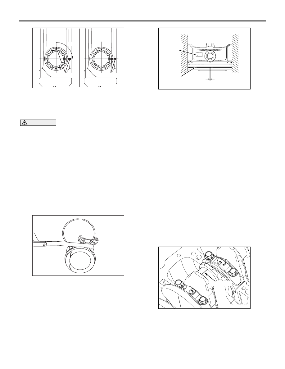
6. Put a paint mark on the bolt head as illustrated.

7. Put a paint mark on the connecting rod at 90

° 

position in the tightening direction of the bolt with 
reference to the paint mark position of the bolt.

CAUTION

• When the tightening angle is smaller than the 

specified tightening angle, the appropriate 
tightening capacity cannot be secured.

• When the tightening angle is larger than the 

specified tightening angle, remove the bolt to 
start from the beginning again according to 
the procedure.

8. Tighten the bolt 90

°, and make sure that the paint 

mark of the connecting rod is aligned with that of 
the bolt.

INSPECTION

M1113008502703

PISTON RINGS

AK502751

1. Check clearance between piston rings and ring 

grooves. If the limit is exceeded, replace piston 
rings or piston, or both.

Standard value:

No. 1 ring: 0.03 

 0.07 mm

No. 2 ring: 0.03 

 0.07 mm

Limit: 0.1 mm

AK503370AG

Press down ring 
with piston

End gap

Piston ring

Front mark

2. Put piston rings into the cylinder bore, press them 

against the piston top face, and push them in. 
After achieving squareness, measure the end gap 
with a thickness gauge. If the end gap is 
excessive, replace piston rings.

Standard value:

No. 1 ring: 0.15 

 0.28 mm <4B11>

No. 1 ring: 0.15 

 0.25 mm <4B12>

No. 2 ring: 0.30 

 0.45 mm <4B11>

No. 2 ring: 0.25 

 0.40 mm <4B12>

Oil ring: 0.10 

 0.35 mm

Limit:

No. 1 ring: 0.8 mm
No. 2 ring: 0.8 mm
Oil ring: 1.0 mm

CRANKSHAFT PIN OIL CLEARANCE 
(PLASTIGAGE METHOD)

1. Wipe oil off the crankshaft pin and connecting rod 

bearing.

2. Place a Plastigage in length equal to the bearing 

width on the pin shaft straight in alignment with 
the shaft centre.

AK503373AC

Plastigage

3. Carefully install the connecting rod cap and 

tighten bolts to the specified torque of 5.0 N

⋅m → 

20 N

⋅m → +90°.

4. Remove bolts and gently remove the connecting 

rod cap.

AK503374AC

Plastigage

CRANKSHAFT AND CYLINDER BLOCK

ENGINE OVERHAUL

11B-59

5. Measure the crushed Plastigage width (area most 

widely crushed) using a scale printed on the 
Plastigage bag.

Standard value: 0.018 

 0.045 mm

Limit: 0.1 mm

CRANKSHAFT AND CYLINDER BLOCK

REMOVAL AND INSTALLATION

M1113008704286

AK604556AC

5

26.5 ± 2.0 N·m   +45˚

6

7

11 ± 1 N·m

8

4

3

2

1

Apply engine oil to
all moving parts
before installation.

Removal steps 

>>E<<

1. Crankshaft bearing cap bolt

>>E<<

2. Crankshaft bearing cap

>>D<<

3. Crankshaft bearing lower

<<A>>

4. Crankshaft

>>C<<

5. Crankshaft bearing upper

>>B<<

6. Thrust bearing

>>A<<

7. Crankshaft sensing ring
8. Cylinder block

CRANKSHAFT AND CYLINDER BLOCK

ENGINE OVERHAUL

11B-60

REMOVAL SERVICE POINT

<<A>> CRANKSHAFT REMOVAL

When temporarily placing the crankshaft with the 
crankshaft sensing ring attached, temporarily place it 
on a V-block to prevent teeth of the sensing ring from 
deforming.

NOTE: If a tooth bends, be sure to replace the crank-
shaft sensing ring with a new one.

INSTALLATION SERVICE POINTS

>>A<< CRANKSHAFT SENSING RING 
INSTALLATION

AKB00121AC

1

2

3

Crankshaft sensing ring

Tighten crankshaft sensing ring bolts to the torque of 
11 

± 1 N⋅m in the tightening order shown in the illus-

tration.

>>B<< THRUST BEARING INSTALLATION 

1. Install the thrust bearing on the No. 3 bearing on 

the cylinder block side. Application of engine oil 
makes the installation easy.

AK502394

Groove

AD

2. Install the thrust bearing so that the grooved side 

is on the crankshaft weight side.

>>C<< CRANKSHAFT BEARING UPPER 
INSTALLATION

J

2

J

3

J

4

J

5

J

1

AK502530

No.1

No.2

No.3

No.4

No.5

AC

1. When replacing the crankshaft bearing upper, 

select a bearing with the size corresponding to the 
cylinder block journal diameter in the table below.

AK502396

Groove

AF

Identification 
mark

2. The crankshaft bearing upper has an identification 

mark at the illustrated position.

Cylinder block

Crankshaft 
bearing

Identification 
mark

Journal 
diameter mm

Identification 
mark

1

56.000 

− 56.006 1

2

56.006 

− 56.012 2

3

56.012 

− 56.018 3

3. Install the selected crankshaft bearing upper.

CRANKSHAFT AND CYLINDER BLOCK

ENGINE OVERHAUL

11B-61

>>D<< CRANKSHAFT BEARING LOWER 
INSTALLATION

AK502528AC

No.1

No.2

No.3

No.4

No.5

Journal identification mark position

1. When replacing the crankshaft bearing lower, 

select a bearing with the size corresponding to the 
crankshaft journal diameter in the table below.

AK502418AF

Identification 
mark

2. The crankshaft bearing lower has an identification 

mark at the illustrated position.

Crankshaft

Crankshaft 
bearing

Identification 
mark

Journal 
diameter mm

Identification 
mark

0

51.985 

− 51.988 0

1

51.982 

− 51.985 1

2

51.979 

− 51.982 2

3

51.976 

− 51.979 3

4

51.973 

− 51.976 4

3. Install the selected crankshaft bearing lower.

>>E<< CRANKSHAFT BEARING CAP / 
CRANKSHAFT BEARING CAP BOLT 
INSTALLATION

AK502395

10

9

6

5

1

2

3

4

7

8

AC

1. Install the crankshaft bearing cap with reference 

to the identification mark as illustrated.

AK402401

AC

Shank length

2. Make sure that the shank length of the bolt is at or 

below the limit before installing the crankshaft 
bearing cap bolt. If the length exceeds the limit, 
replace the bolt with a new one.

Limit: 75.5 

 76.5 mm

3. Apply engine oil to the threaded portion and seat 

surface of the bolt.

4. Tighten crankshaft bearing cap bolts to the torque 

of 26.5 

± 2.0 N⋅m according to the tightening 

order.

AK502750

45˚

MB991614

AC


Content   ..  274  275  276  277   ..