Mitsubishi Outlander (2013+). Manual - part 272
AK503333AC
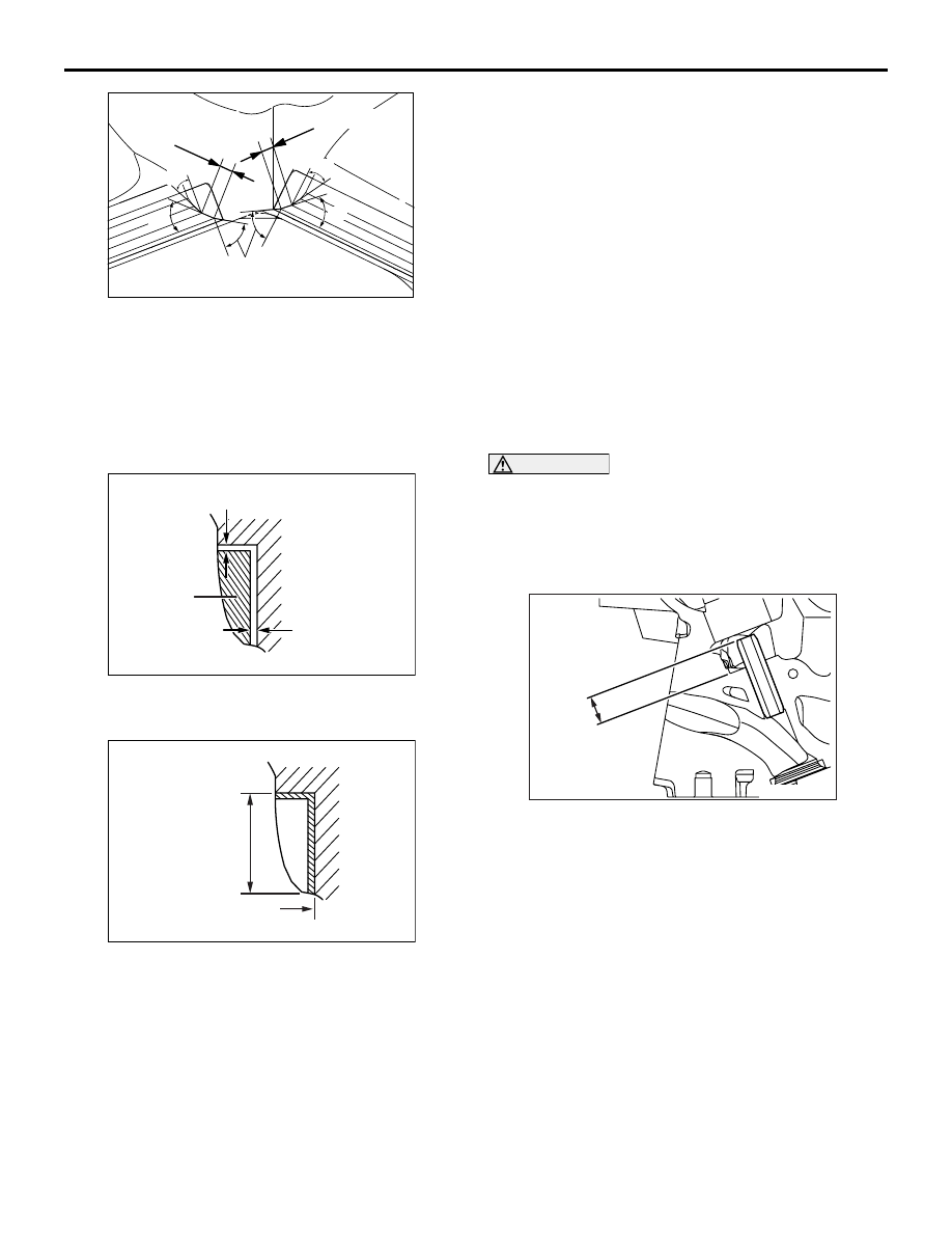
30˚
60˚
30˚
1.35 – 1.65 mm
1.16 – 1.46 mm
45˚
45˚
CYLINDER HEAD AND VALVES
ENGINE OVERHAUL
11B-42
2. Repair the valve seat so that seat width and seat
angle are to the specified shape.
3. Lap valve and valve seat with lapping compound
after repairing valve seat.
REPLACEMENT PROCEDURE OF VALVE
SEAT
AK300719AB
0.5 – 1 mm
0.5 – 1 mm
Cut
1. Scrape the valve seat to be replaced from inside
to make its wall thickness thin before pulling out.
AK300720AB
Oversize hole diameter
Valve seat
height
2. Repair the valve seat hole of the cylinder head to
match it with the diameter of the oversize valve
seat to be press fitted.
Inlet valve seat bore diameter:
0.3 O.S.: 36.22
− 36.24 mm
Exhaust valve seat bore diameter:
0.3 O.S.: 30.22
− 30.24 mm
3. Press fit the valve seat, taking care not to score
the cylinder head bore at room temperature.
4. Ream the valve seat.
Refer to "Repair procedure of valve seat."
REPLACEMENT PROCEDURE OF VALVE
GUIDE
1. Pull out the valve guide with a press toward the
cylinder block side.
2. Ream the valve guide hole of the cylinder head to
match it with the diameter of the oversize valve
guide to be press fitted.
CAUTION
Do not use a valve guide with the same size as
that of the pulled out valve guide because it can-
not be press fitted.
Valve guide bore diameter
0.25 O.S.: 11.23
− 11.25 mm
AK603511AC
14.6 – 15.2 mm
3. Press fit the valve guide to the illustrated
dimension.
Standard value: 14.6
− 15.2 mm
NOTE: Press fit the valve guide from the cylinder
head top surface.
4. After pressing fit the valve guide, insert a new
valve to check for sliding.