Mitsubishi Outlander (2013+). Manual - part 270
AK502390
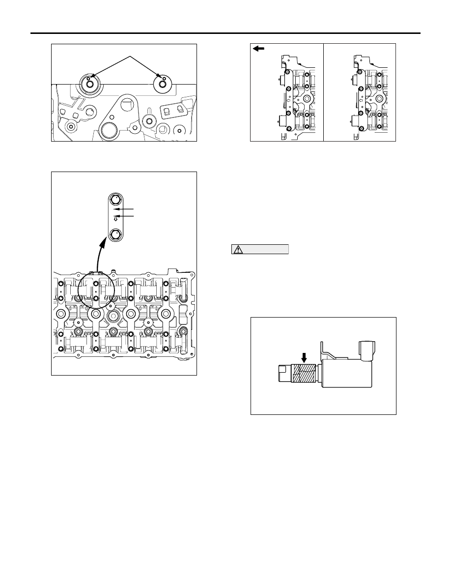
Dowel pin
AC
CAMSHAFT
ENGINE OVERHAUL
11B-34
4. Set the dowel pins of the camshaft at the
illustrated positions.
AK503813
2
E
Cap No.
1
2
6
5
2
1
6
5
AC
8
7
4
3
8
7
4
3
Identification mark
5. Install them upon checking the identification mark
so as not to misidentify cap No. and to confuse
the inlet side with the exhaust side.
Identification mark
I: Inlet side
E: Exhaust side
6. Tighten each camshaft bearing cap mounting bolt
to the specified torque of 12
± 1 N⋅m in the order
of number shown in the figure in two or three
steps.
AK503814
4
3
2
1
1
3
4
2
(1)
(2)
AC
Timing chain side
7. Tighten each front camshaft bearing cap
mounting bolt to the temporarily torque of 17
± 3
N
⋅m in the order of number shown (1).
8. Tighten each front camshaft bearing cap
mounting bolt to the specified torque of 30
± 2
N
⋅m in the order of number shown (2).
>>C<< O-RING / OIL FEEDER CONTROL
VALVE INSTALLATION
CAUTION
• The O-ring must not be reused.
•
AK303651AE
Tape
Wind non-adhesive tape (seal tape, etc.)
around the notch of the oil passage of the oil
feeder control valve before installing the
O-ring to prevent damage. Damage to the
O-ring causes oil leakage.
1. Apply a small amount of engine oil to the O-ring of
the oil feeder control valve.
2. Install the oil feeder control valve on the cylinder
head.
3. Tighten the oil feeder control valve to the specified
torque of 10
± 2 N⋅m.