Mitsubishi Outlander (2013+). Manual - part 271


  Index      Mitsubishi     Mitsubishi Outlander - service repair manual 2013 year


Search            


Content   ..  269  270  271  272   ..


Mitsubishi Outlander (2013+). Manual - part 271


CYLINDER HEAD AND VALVES

ENGINE OVERHAUL

11B-38

REMOVAL SERVICE POINTS

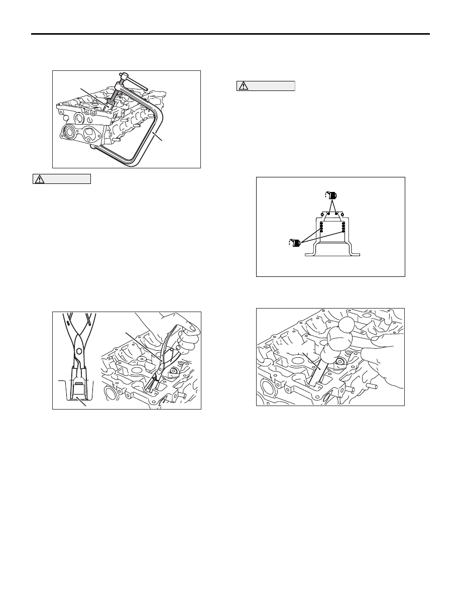
<<A>> RETAINER LOCK REMOVAL

AK502741AC

MB992089

MD998735

CAUTION

Be careful not to allow retainer holder C to inter-
fere with the wall of the tappet hole and to dam-
age it.
Use a special tool to compress the valve spring and 
to remove the retainer lock.

• Valve spring compressor (MD998735)

• Retainer holder C (MB992089)

NOTE: Store removed parts such as valves and 
springs with tags describing cylinder No. and 
installed position attached for reassembly.

<<B>> VALVE STEM SEAL REMOVAL

AK502782AC

Valve stem seal

MB992085

Use special tool Valve stem seal pliers (MB992085) 
to firmly pinch the base (larger external shape) of the 
stem seal and twist it right and left for pulling out.

INSTALLATION SERVICE POINTS

>>A<< VALVE STEM SEAL INSTALLA-
TION

CAUTION

• The valve stem seal must not be reused.
• Do not damage the tappet wall during assem-

bly.

• Be sure to use a special tool to install the 

valve stem seal. Poor installation causes oil 
loss via valve guides.

AK503378 AD

If oil is not applied, the valve stem seal may 
rise to the surface after it is press fitted.

1. Apply a thin coat of engine oil to a new valve stem 

seal.

AK502742AC

MD998737

2. Use special tool Valve stem seal installer 

(MD998737) to press fit the valve stem seal into 
the valve guide with the valve stem used as a 
guide.

CYLINDER HEAD AND VALVES

ENGINE OVERHAUL

11B-39

>>B<< RETAINER LOCK INSTALLATION

AK502741AC

MB992089

MD998735

Use a special tool to compress the valve spring and 
to install the retainer lock.

• Valve spring compressor (MD998735)

• Retainer holder C (MB992089)

>>C<< CYLINDER HEAD GASKET / 
CYLINDER HEAD ASSEMBLY 
INSTALLATION

AK602902AC

Top face of cylinder block 

Degrease

Degrease

Bottom face of cylinder head 

1. Completely remove the liquid gasket on the upper 

plane of the cylinder block and the lower plane of 
the cylinder head.

CAUTION

Sufficiently check that there is no residual oil on 
the place where degreasing is performed. If fin-
gerprints are left, do not touch it with bare hands 
after the degreasing, since the oils from your fin-
gers will harm the seal ability.

2. Degrease the place specified in the illustration.

AK602942AC

Ø2 to Ø3 mm

Timing chain side

3. As shown in the illustration, apply a 2.5 

± 0.5 mm 

of sealant to the top face of cylinder block.

Specified sealant:

ThreeBond 1217G or equivalent

4. Install the cylinder head gasket.

NOTE: Check that the centre of the liquid gasket 
is located toward the cylinder gasket in the posi-
tion specified in the illustration.

5. As shown in the illustration, apply a 2.5 

± 0.5 mm 

of sealant to the top face of cylinder head gasket.

Specified sealant:

ThreeBond 1217G or equivalent

6. Install the cylinder head assembly.

>>D<< CYLINDER HEAD BOLT 
INSTALLATION

1. Install new cylinder head bolts and washers in the 

following procedure.

NOTE:  Cylinder head bolts and washers must not 
be reused.

2. Apply an appropriate amount of engine oil to top 

and bottom surfaces of washers and threaded 
portion of bolts.

3. Install cylinder head bolts to the cylinder head.

CYLINDER HEAD AND VALVES

ENGINE OVERHAUL

11B-40

NOTE: Bolts and washers are different parts for 
bolts on the timing chain side.

AK502392

8

10

9

7

3

5

1

2

6

4

AC

Timing chain side

4. Tighten cylinder head bolts in several steps to the 

specified torque of 35 

± 2 N⋅m according to the 

assembly order.

AK502523AC

Paint mark

Paint mark

90˚

90˚

Paint mark

Paint mark

5. Put a paint mark on all of cylinder head bolt heads 

and cylinder head.

CAUTION

• When the tightening angle is smaller than the 

specified tightening angle, the appropriate 
tightening capacity cannot be secured.

• When the tightening angle is larger than the 

specified tightening angle, remove the bolt to 
start from the beginning again according to 
the procedure.

6. Tighten the cylinder head 90

° according to the 

tightening order.

Tighten it further 90

° and make sure that the paint 

mark on the cylinder head bolt is in a straight line 
with that on the cylinder head.

INSPECTION

M1113007003106

CYLINDER HEAD

1. Check the cylinder head for water leakage, gas 

leakage, damage or cracks before cleaning.

2. Completely remove oil, scale, sealant, carbon, 

etc. After cleaning oil passages, blow air to make 
sure that they are not clogged.

AK502740

CAUTION

The grinding limit shall be within 0.2 mm in com-
bination with the cylinder block to be assembled.
3. For the flatness on the cylinder head bottom, 

measure distortion using a straight edge and free 
gauge. If the distortion exceeds the limit, grind 
and repair it.

Distortion on bottom

Standard value: Within 0.05 mm
Limit: 0.2 mm
Grinding limit: 0.2 mm

Cylinder head height: 128.5 mm

VALVE

AK305408AB

Margin

The bottom of valve
seat contact facet

1. Repair the valve seat if contact with the valve seat 

is poor, uneven or broken.

2. Measure the margin.

If the limit is exceeded, replace the valve.

Standard value:

Inlet 1.022 mm
Exhaust 1.094 mm

Limit:

Inlet 0.522 mm
Exhaust 0.594 mm

AK305409AB

Length

CYLINDER HEAD AND VALVES

ENGINE OVERHAUL

11B-41

3. Measure overall length of the valve.

If the limit is exceeded, replace the valve.

Standard value:

Inlet 113.18 mm
Exhaust 105.89 mm

Limit:

Inlet 112.68 mm
Exhaust 105.39 mm

VALVE SPRING

AK305410AB

Free height

Squareness

1. Measure free height of the spring.

If the limit is exceeded, replace the spring.

Standard value: 49.4 mm
Limit: 48.4 mm

2. Measure squareness of the spring.

If the inclination exceeds the limit, replace the 
spring.

Standard value: 2

° or less

Limit: 4

°

VALVE GUIDE

AK300168

Guide inside diameter

Stem diameter

Valve 
guide

AE

Measure clearance between the valve guide and 
valve stem. If the clearance exceeds the limit, 
replace the valve guide or valve, or both.

Standard value:

Inlet 0.020 

 0.047 mm

Exhaust 0.030 

 0.057 mm

Limit:

Inlet 0.10 mm
Exhaust 0.15 mm

VALVE SEAT

AK601281AC

Valve seat

Contact width

Assemble the valve, then measure the contact width. 
If the measurement exceeds the specified limit, 
replace the valve seat.

Standard value

Inlet: 1.16 

 1.46 mm

Exhaust: 1.35 

 1.65 mm

CAUTION

If the variation in the width exceeds 0.2 mm even 
if the contact width is within the standard value, 
replace or correct the valve sheet.

REPAIR PROCEDURE OF VALVE SEAT

1. Check clearance between valve guide and valve 

and replace the valve guide if necessary before 
repairing the valve seat.


Content   ..  269  270  271  272   ..