Mitsubishi Outlander (2013+). Manual - part 253


  Index      Mitsubishi     Mitsubishi Outlander - service repair manual 2013 year


Search            


Content   ..  251  252  253  254   ..


Mitsubishi Outlander (2013+). Manual - part 253


VALVE STEM SEAL

ENGINE MECHANICAL

11A-35

>>E<< CAMSHAFT BEARING/CAMSHAFT 
AND CAMSHAFT SPROCKET ASSEMBLY 
(EXHAUST SIDE) INSTALLATION

CAUTION

• Be careful not to drop the camshaft bearing.

AC611697

AC

Camshaft
bearing
front cap
assembly

Identification 
mark

AC708893

Notch

Identification mark

Oil hole

AE

When installing the camshaft and camshaft 
sprocket assembly (exhaust side), be careful 
not to let the camshaft bearing which is 
installed to the front cam bearing deviate from 
its position.

When replacing the camshaft bearing, select a cam-
shaft bearing in relevant size according to the cam-
shaft bearing front cap identification mark in the table 
below. Identification mark of the camshaft bearing is 
painted in the position shown in the figure.

Camshaft

Camshaft 
bearing 
identification 
mark

Identification 
mark

Journal diameter 
mm

1

40.000 

− 40.008

1

2

40.008 

− 40.016

2

3

40.016 

− 40.024

3

>>F<< CAMSHAFT BEARING FRONT CAP 
ASSEMBLY INSTALLATION

CAUTION

When the mounting bolts are tightened with the 
camshaft bearing front cap tilted, the camshaft 
bearing front cap is damaged. Install the cam-
shaft bearing front cap properly to the cylinder 
head and camshaft.

AC511062

AB

4

3

2

1

4

3

2

1

(1)

(2)

Engine front

Camshaft
bearing
front cap
assembly

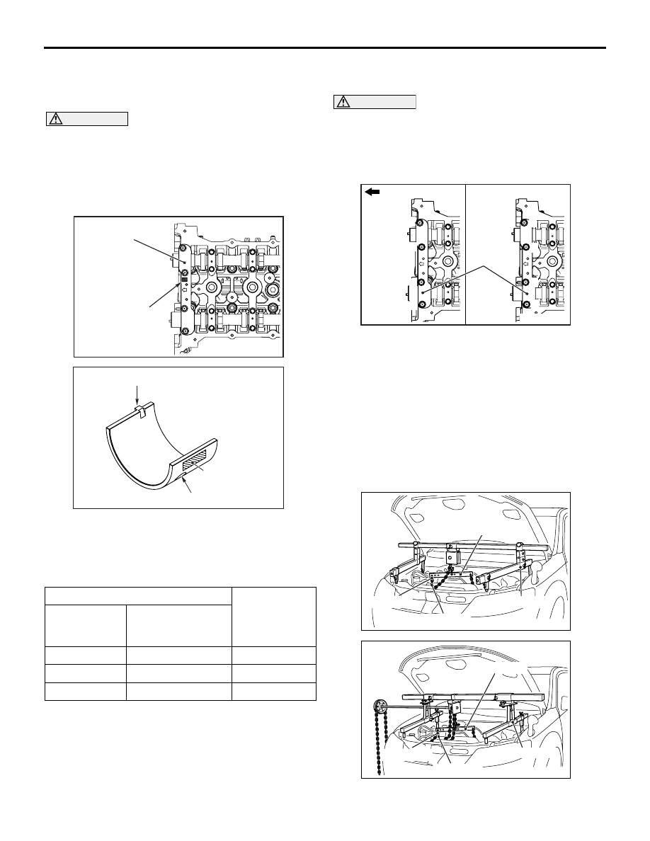
1. Install the camshaft bearing front cap to the 

cylinder head, and temporarily tighten the 
camshaft bearing front cap mounting bolts to the 
specified torque in the order shown in the figure 
(1).

Tightening torque: 17 

± 3 Nm

2. Tighten again the camshaft bearing front cap 

mounting bolts to the specified torque again in the 
order shown in the figure (2).

Tightening torque: 30 

± 2 Nm

AC506487

AD

MB991527

MB991454

MB991928

MB991956

AC506484

MB991527

AD

MB991454

MB991956

MB991895

OIL PAN

ENGINE MECHANICAL

11A-36

3. Install special tool engine hanger (MB991928 or 

MB991895) which was installed for supporting the 
engine and transmission assembly when the 
valve timing chain was removed (Refer to 

P.11A-50

).

4. Remove the garage jack which supports the 

engine and transmission assembly.

5. Remove the engine oil pan installed temporarily.

OIL PAN

REMOVAL AND INSTALLATION

M1112002803416

Pre-removal Operation
• Engine Room Under Cover Front A, B and Engine Room 

Side Cover (RH) Removal (Refer to GROUP 51 

− Under 

Cover ).

• Engine Oil Draining (Refer to GROUP 12 − On-vehicle 

Service, Engine Oil Replacement ).

• Alternator and Others Belt Removal (Refer to 

P.11A-16

).

Post-installation Operation
• Alternator and Others Belt Installation (Refer to 

P.11A-16

).

• Engine Oil Refilling (Refer to GROUP 12 − On-vehicle 

Service, Engine Oil Replacement ).

• Engine Room Under Cover Front A, B and Engine Room 

Side Cover (RH) Installation (Refer to GROUP 51 

− Under 

Cover ).

ACC00061

10 ± 2 N·m

23 ± 6 N·m

31 ± 2 N·m

39 ± 5 N·m

23 ± 6 N·m

1

7

6

5

4

N

23 ± 6 N·m

23 ± 6 N·m

2

3

AB

Removal steps 

1.

A/C compressor and clutch 
connector connection

<<

A

>>

>>

B

<<

2.

A/C compressor and clutch 
assembly

3.

A/C compressor bracket A

4.

A/C compressor bracket B

5.

Engine oil pan drain plug

6.

Engine oil pan drain plug gasket

<<

B

>>

>>

A

<<

7.

Engine oil pan

OIL PAN

ENGINE MECHANICAL

11A-37

REMOVAL SERVICE POINTS

<<A>> A/C COMPRESSOR AND CLUTCH 
ASSEMBLY REMOVAL

1. Remove the A/C compressor and clutch assembly 

together with the hose from the bracket.

2. Tie the removed A/C compressor and clutch 

assembly with a string at a position where they 
will not interfere with the removal and installation 
of engine oil pan.

<<B>> ENGINE OIL PAN REMOVAL

1. Remove the engine oil pan mounting bolts.

CAUTION

Do not forcibly drive in special tool oil pan FIPG 
cutter (MD998727) to avoid damage to the engine 
oil pan seal surface of cylinder block assembly.

AC506757

AB

<Engine front>

Engine oil pan

Crankshaft pulley

AC506758

AB

Engine oil filter

Engine oil pan

<Engine rear>

AC102324 AB

MD998727

MD998727

2. Insert special tool oil pan FIPG cutter (MD998727) 

from the engine oil pan removal groove of the 
cylinder block assembly. 

3. Lightly tap the special tool (MD998727) with a 

hammer to slide the engine oil pan seal surface, 
cut off the liquid gasket, and remove the engine oil 
pan.

INSTALLATION SERVICE POINTS

>>A<< ENGINE OIL PAN INSTALLATION

1. Remove all the traces of sealant adhering to the 

engine oil pan and cylinder block assembly using 
a remover or others. Then, degrease them.

AC506756AB

1mm


2 mm or


3 mm

OIL PAN

ENGINE MECHANICAL

11A-38

2. Apply the sealant without any gap to the mating 

surface of engine oil pan as shown in the figure, 
and install the engine oil pan to the cylinder block 
assembly.

Specified sealant: ThreeBond 1217G or 
equivalent

NOTE: Install the engine oil pan immediately after 
applying sealant.

CAUTION

After the installation, until a sufficient period of 
time (one hour or more) elapses, do not apply the 
oil or water to the sealant application area or 
start the engine.

3. Tighten the engine oil pan mounting bolts to the 

specified torque.

Tightening torque: 

M6: 10 

± 2 Nm

M8: 29 

± 2 Nm

>>B<< A/C COMPRESSOR AND CLUTCH 
ASSEMBLY INSTALLATION

AC506759

AK

1

2

3

A/C compressor 
and clutch assembly

Tighten A/C compressor and clutch assembly mount-
ing bolts to the specified torque in the order of 
number shown in the illustration.

Tightening torque: 23 

± 6 Nm

INSPECTION

M1112002900920

• Check the engine oil pan for cracks.

• Check the engine oil pan sealant-coated surface 

for damage and deformation.


Content   ..  251  252  253  254   ..