Mitsubishi Outlander (2013+). Manual - part 251
CAMSHAFT
ENGINE MECHANICAL
11A-27
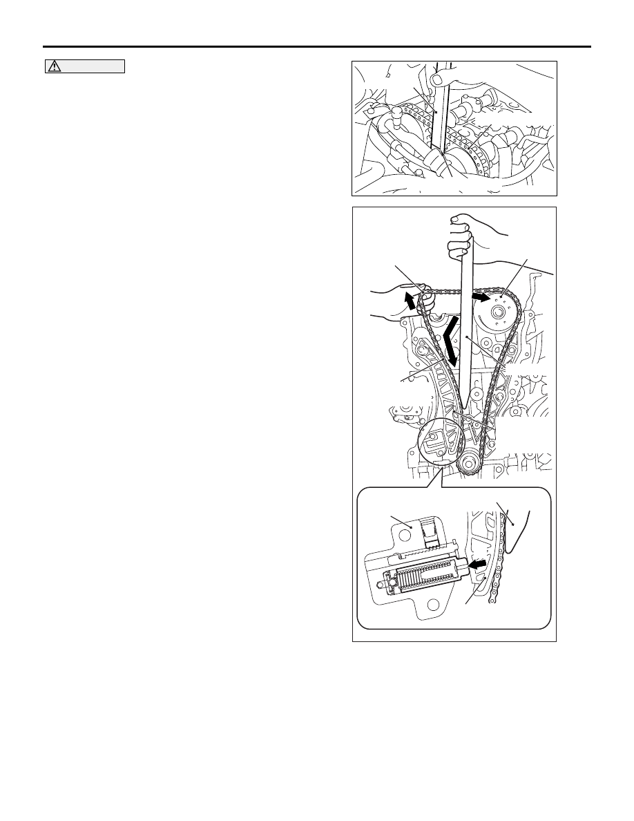
CAUTION
• When inserting special tool chain tension
release bar (MB992103) into the timing chain
case assembly inside, pay attention to the
position of the valve timing chain to avoid
damage to the valve timing chain and timing
chain tension side guide. Do not insert the
special tool MB992103 beyond its insertion
guideline.
• If unlocking the timing chain tensioner is
insufficient, the special tool MB992103 cannot
be inserted to the insertion guideline. Do not
insert the special tool MB992103 forcibly, fol-
low Step 2 again to unlock the timing chain
tensioner and insert the special tool
MB992103.
AC507118
AB
Valve timing chain
MB992103
Insertion standard line
AC509177
AC508125
AB
MB992103
MB992103
Timing chain
tensioner
Timing chain
tension side guide
Timing chain
tension
side guide
Valve timing chain
(tension side)
Camshaft
sprocket
(inlet side)
Valve timing chain
(exhaust camshaft and
camshaft sprocket
assembly side)
A
B
C
D
3. With the timing chain tensioner unlocked, insert
special tool chain tension release bar
(MB992103) from the timing chain case assembly
inside along the tension side of the valve timing
chain until the insertion guide line aligns with the
upper surface of the timing chain case assembly
(A in the figure).