Mitsubishi Outlander (2013+). Manual - part 249
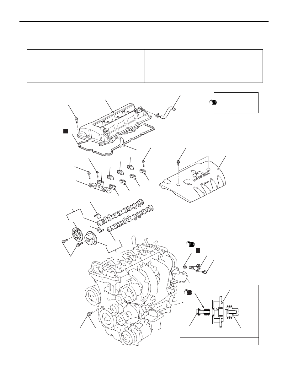
CAMSHAFT
ENGINE MECHANICAL
11A-19
CAMSHAFT
REMOVAL AND INSTALLATION
M1112023100866
Pre-removal Operation
• Engine Room Under Cover Front A, B and Engine Room
Side Cover (RH) Removal (Refer to GROUP 51
− Under
Cover ).
• Air Cleaner Assembly Removal (Refer to GROUP 15 − Air
Cleaner ).
Post-installation Operation
• Air Cleaner Assembly Installation (Refer to GROUP 15 −
Air Cleaner ).
• Engine Room Under Cover Front A, B and Engine Room
Side Cover (RH) Installation (Refer to GROUP 51
− Under
Cover ).
ACB01329
2
13
12
9
15
3
AB
59 ± 5 N·m
4
14
3.0 ± 0.5 N·m
24
10 ± 2 N·m
7
1
10
11
3.0 ± 1.0 N·m 5.5 ± 0.5 N·m
23
22
12 ± 1 N·m
17 ± 3 N·m 30 ± 2 N·m
12 ± 1 N·m
25
N
6
13 ± 1 N·m
5
N
Apply engine oil to all
moving parts before
installation.
(Engine oil)
AC607720
Engine oil
V.V.T.
sprocket bolt
23
22
18
17
19
20
8
21
16