Mitsubishi Outlander (2013+). Manual - part 247
ON-VEHICLE SERVICE
ENGINE MECHANICAL
11A-11
8. If the basic ignition timing is outside the standard
value, inspect the MPI system (Refer to GROUP
13A
− Troubleshooting − Inspection chart for
trouble symptom ).
CAUTION
If the test is not cancelled, a forced driving will
continue for 27 minutes. Driving under this con-
dition may damage the engine.
9. Cancel the actuator test function item No. 11,
Basic ignition timing set mode, on the M.U.T-III.
10.Check that ignition timing is at the standard value.
Standard value: approximately 10
° BTDC
NOTE:
.
•
The ignition timing may fluctuate within
±
7
°
.
This is normal.
•
In higher altitude, the ignition timing is more
advanced than the standard value by approxi-
mately 5
°
.
•
Wait till approximately 1 minute passes after
the engine started, and check the ignition tim-
ing when the engine stabilized.
11.Remove the timing light.
12.Turn the ignition switch to the "LOCK" (OFF)
position and then disconnect the M.U.T.-III.
IDLE SPEED CHECK
M1111003503329
ACB05017
MB992747, MB992748, MB991827
MB992744, MB991824
AB
MB992745, MB991910
Diagnosis connector
1. Before inspection, set the vehicle to the
pre-inspection condition.
2. Turn the ignition switch to "LOCK" (OFF) position.
3. Connect the M.U.T.-III to the diagnosis connector.
AK604618
3
2
1
3
2
1
AC
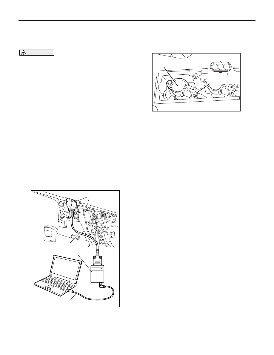
Power supply line
(terminal No. 3)
No.1 Ignition coil
Equipment side connector
4. Set the timing light to the power supply line
(terminal No. 3) of the ignition coil No. 1.
5. Start the engine and let it run at idle.
6. Check that ignition timing is at the standard value.
Standard value: approximately 10
° BTDC
NOTE:
.
•
The ignition timing may fluctuate within
±
7
°
.
This is normal.
•
In higher altitude, the ignition timing is more
advanced than the standard value by approxi-
mately 5
°
.
•
Wait till approximately 1 minute passes after
the engine started, and check the ignition tim-
ing when the engine stabilized.
7. Check the idle speed.
Standard value:
650
± 100 r/min <4B11>
750
± 100 r/min <4B12>
NOTE:
.
•
The idle speed is controlled automatically by
the idle speed control system.
•
When using the M.U.T.-III, select item No. 2
and take a reading of the idle speed.
8. If the idle speed is outside the standard value,
inspect the MPI system (Refer to GROUP 13A
−
Troubleshooting
− Inspection chart for trouble
symptom ).
9. Remove the timing light.
10.Turn the ignition switch to the "LOCK" (OFF)
position and then disconnect the M.U.T.-III.