Mitsubishi Outlander (2013+). Manual - part 246
B991454
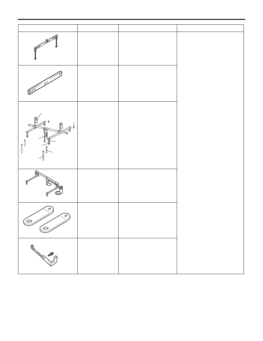
SPECIAL TOOLS
ENGINE MECHANICAL
11A-7
MB991454
Engine hanger balancer
Support of engine assembly
NOTE:
.
•
For the engine hanger
balancer (MB991454), use a
chain only.
•
Engine hanger balancer
(MB991454) is a part of the
engine hanger assembly
(MB991453).
B991527
MB991527
Hanger
B991928
a
b
c
d
e
f
Slide bracket (HI)
AI
MB991928
a: MB991929
b: MB991930
c: MB991931
d: MB991932
e: MB991933
f: MB991934
Engine hanger
a: Joint (50)
× 2
b: Joint (90)
× 2
c: Joint (140)
× 2
d: Foot (standard)
× 4
e: Foot (short)
× 2
f: Chain and hook
assembly
Z203830
MB991895
Engine hanger
B991956
MB991956
Engine hanger plate
B992853
MB992853
Engine hanger plate
Tool
Number
Name
Use