Mitsubishi Outlander (2013+). Manual - part 9
BODY DIMENSIONS AND MEASUREMENT METHODS
BODY DIMENSIONS
2-2
BODY DIMENSIONS AND MEASUREMENT METHODS
M4020001000448
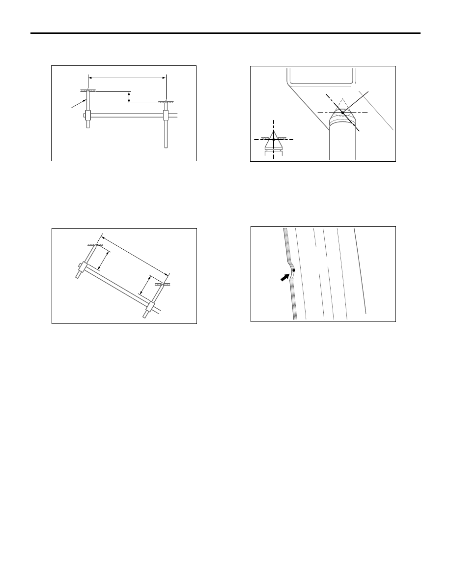
•
Type A (projected dimensions) is the dimension
when a measurement location is projected onto
the plane.
NOTE: The height indicates a distance from the
assumed standard line established 100 mm
below the lowest measurement point.
•
Type B (actual-measurement dimensions) is the
actual distance between the measurement
points. Measure using a tracking gauge or a
measuring tape, etc.
NOTE:
.
•
Make the lengths of the tracking gauge
probes the same (A=A’).
•
Do not bend or twist the measuring tape.
•
Insert the tracking gauge probes securely into the
measurement holes.
• When the standard dimensions in the illustration
are enclosed by rectangle, this indicates that the
symmetrical left and right positions have the
same dimensions.
•
When using a notch for dimension measurement, set
the measuring point at the centre of the outer
panel notch.
• The body centre points are shown for the pur-
pose of checking the position of the left and right
symmetry location.
AB302138
AE
Probe
Height
Projected dimension
AB302139
AE
A'
A
Actual-measured
dimension
AB302140
AF
Centre of hole
AB302141
AD