Mitsubishi Outlander (2003+). Manual - part 525
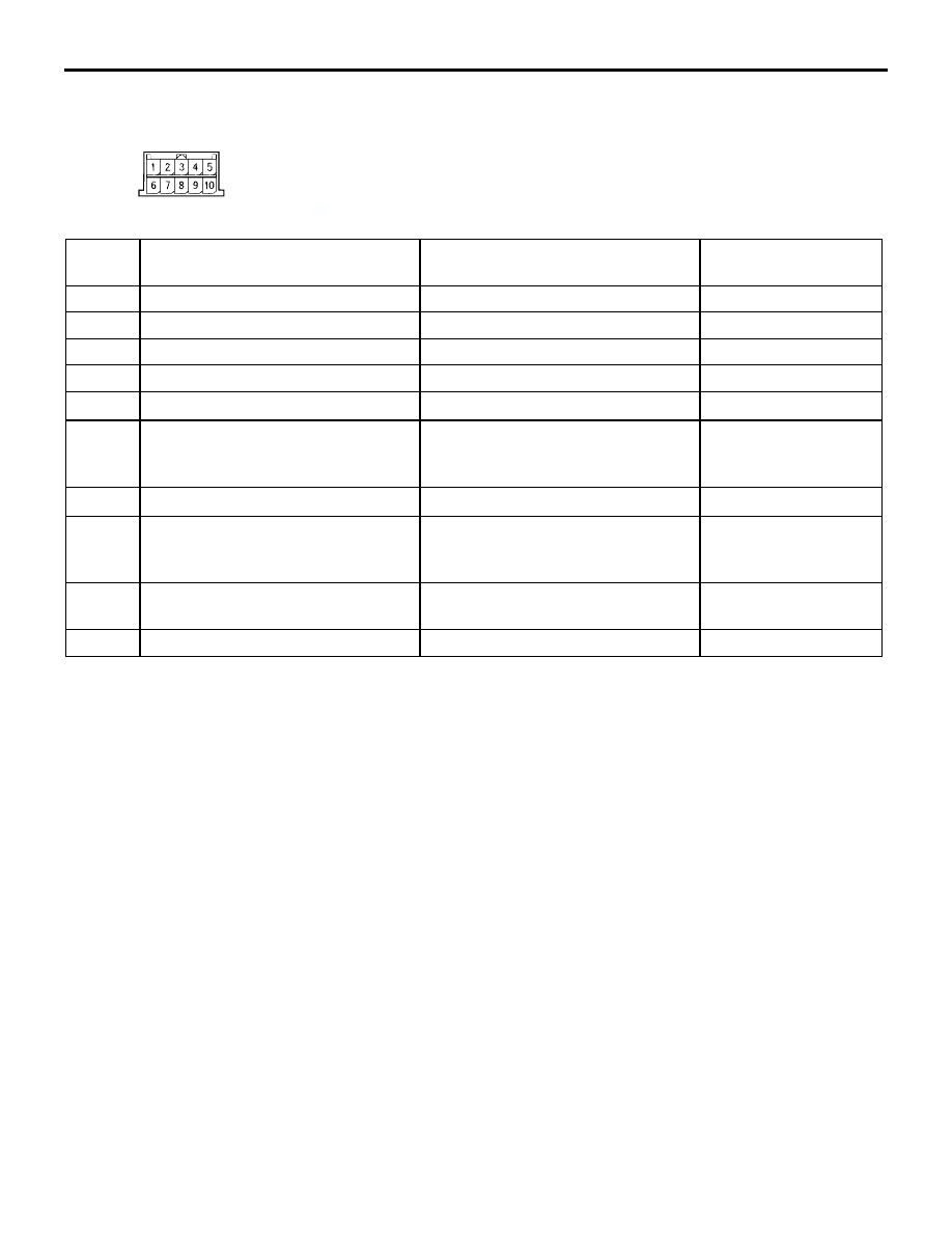
CHECK AT ECU TERMINAL
SMART WIRING SYSTEM (SWS) NOT USING SWS MONITOR
54B-389
Column switch
AC005555AF
C-310
Termin
al No.
Check item
Check condition
Normal condition
1
System voltage
Always
System voltage
2
Input of SWS request signal
Always
0 to 12 V (pulse signal)
3
SWS communication line
Always
0 to 12 V (pulse signal)
4
Earth
Always
0 V
5
−
−
−
6
Output to windshield intermittent
wiper volume
Ignition switch: ACC
Move the wiper volume from "Fast"
to "Slow."
0 to 2.5 V
7
−
−
−
8
Back-up output to windshield wiper
switch
Windshield low-speed wiper switch
or windshield high-speed wiper
switch: ON
0 V
9
Power supply from ignition switch
(IG1)
Ignition switch: ON
System voltage
10
Back-up output to headlamp switch Headlamp switch: ON
0 V