Mitsubishi Outlander (2003+). Manual - part 524


  Index      Mitsubishi     Mitsubishi Outlander - service repair manual 2003 year


Search            


Content   ..  522  523  524  525   ..


Mitsubishi Outlander (2003+). Manual - part 524


INPUT SIGNAL PROCEDURES

SMART WIRING SYSTEM (SWS) NOT USING SWS MONITOR

54B-385

Q: Is the check result normal?

YES : 

Intermittent malfunction. (Refer to GROUP 

00 

 How to Cope with Intermittent 

Malfunction 

P.00-6

).)

NO : 

Repair the wiring harness.

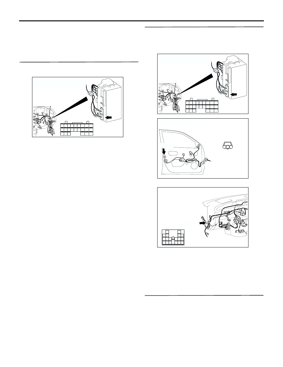
Step 5. Connector check: C-220 ETACS-ECU 
connector

Q: Is the check result normal?

YES : 

Go to Step 6.

NO : 

Repair the defective connector.

Step 6. Check the wiring harness from E-04 door 
lock key cylinder switch (LH) connector terminal 
Nos. 1 and 3 to C-220 ETACS-ECU connector 
terminal Nos. 27 and 28.

NOTE: 

Prior to the wiring harness inspection, check 
intermediate connector C-34, and repair if necessary.

Check the input line for open circuit.

Q: Is the check result normal?

YES : 

Go to Step 7.

NO : 

Repair the wiring harness.

Step 7. Retest the system.

Check that the passenger's door lock key cylinder 
switch signal is received normally.

Q: Is the check result normal?

YES : 

Intermittent malfunction. (Refer to GROUP 

00 

 How to Cope with Intermittent 

Malfunction 

P.00-6

).)

NO : 

Replace the ETACS-ECU.

AC308776

Connector: C-220 <RHD>

Junction block (Rear view)

AF

Harness side

28

37

43

29

44

38

23

32

41

24

25

26

27

34

42

3635

33

21

22

30

39

40

31

AC308776

Connector: C-220 <RHD>

Junction block (Rear view)

AF

Harness side

28

37

43

29

44

38

23

32

41

24

25

26

27

34

42

3635

33

21

22

30

39

40

31

AC308805

Connector: E-04
<RHD>

Harness side

AB

3

1

2

E-04(B)

AC308735

Connector: C-34
<RHD>

AG

C-34(GR)

13

3

7

16

19

15

14

18

17

12

6

4

8

1

9

11

10

5

2

CHECK AT ECU TERMINAL

SMART WIRING SYSTEM (SWS) NOT USING SWS MONITOR

54B-386

CHECK AT ECU TERMINAL

M1549001200759

ETACS-ECU

NOTE: Terminal numbers 1 to 20 can not be measured as the ETACS-ECU is mounted on the junction block 
directly. The values are for reference only.

AC005554 AH

C-217

C-220

C-219

Terminal 
No.

Check item

Check condition

Normal condition

1

Output to the power window relay

When the power windows are 
operative

System voltage

2

Power supply to the central door 
locking system (battery positive 
voltage)

Always

System voltage

3

Earth (for ECU)

Always

0 V

4

Ignition switch (ACC)

Ignition switch: ACC

System voltage

5

Output to room lamp

When the room lamp is on

2 V or less

6

Power supply to interior lamp 
(battery positive voltage)

Always (when the interior lamp off 
function is off)

System voltage

7

Input from all the door switches

One of the door switches: ON (door 
open)

0 V

8

Power supply from ignition switch 
(IG1)

Ignition switch: ON

System voltage

9

Output to right turn-signal lamps

When right turn-signal lamps are on System voltage

10

Input from driver's door switch

Driver's door switch: ON (door 
open)

0 V

11

Power supply to hazard warning 
lamp (battery positive voltage)

Always

System voltage

12

Output to central door locking (for 
locking the doors)

When the door lock actuators lock 
the doors

System voltage

13

Output to central door locking (for 
unlocking the doors other than the 
driver's door)

When the door lock actuators 
unlock the doors

System voltage

14

Output to left turn-signal lamps

When the left turn-signal lamps are 
on

System voltage

15

16

Output to rear wiper

When rear wiper is operating

System voltage

17

Input of rear wiper automatic stop 
signal

When rear wiper is operating

System voltage

18

Power supply from ignition switch 
(ACC)

Ignition switch: ACC

System voltage

CHECK AT ECU TERMINAL

SMART WIRING SYSTEM (SWS) NOT USING SWS MONITOR

54B-387

19

20

Battery power supply (for ECU)

Always

System voltage

21

Input from rear fog lamp switch

Rear fog lamp switch: ON

0 V

22

Output to central door locking (for 
unlocking the driver's door)

When the door lock actuators 
unlock the doors

System voltage

23

Rear washer output

When rear washer is operating

System voltage

24 to 28

29

Input of collision signal

30

Input to key reminder switch

Key reminder switch: ON (ignition 
key removed)

0 V

31 to 34

35

Input to driver's door lock actuator 
(lock switch)

Driver's door lock: Locked

0 V

36

Input to driver's door lock actuator 
(unlock switch)

Driver's door lock: Unlocked

0 V

37, 38

39

Input to back-up lamp switch

Sift lever: R
Ignition switch: ON

System voltage

Input to inhibitor switch ("R" 
position)

Selector lever: R
Ignition switch: ON

40 to 44

51

Setting diagnosis code or sending 
input check signal

When diagnosis code is set (the 
MUT-II/III is connected or the 
diagnosis connector No.1 is 
earthed)

0 to 12 V (pulse signal)

When input check signal is sent

0 V, 12 V (input signal 
is fluctuating)

52

53

Output to door-ajar indicator lamp

When door-ajar indicator lamp is on 0 V

54

Input from front fog lamp switch

Front fog lamp switch: ON

0 V

55

Input from hazard warning lamp 
switch

Hazard warning lamp switch: ON

0 V

56

Earth (for sensor)

Always

0 V

57, 58

59

SWS communication line

Always

0 to 12 V (pulse signal)

60 to 62

63

Input of vehicle speed signal

When the vehicle is being driven

0 to 12 V (pulse signal)

64, 65

66

Input from windshield intermittent 
wiper volume

Turn the ignition switch to the ACC 
position, and move the wiper 
volume from "Fast" to "Slow."

0 to 2.5 V

67

Input from diagnosis control

When MUT-II/III is connected

0 V

Terminal 
No.

Check item

Check condition

Normal condition

CHECK AT ECU TERMINAL

SMART WIRING SYSTEM (SWS) NOT USING SWS MONITOR

54B-388

68

Input of SWS request signal

Always

0 to 12 V (pulse signal)

69

Output to ignition key cylinder 
illumination lamp

When ignition key cylinder 
illumination is on

2 V or less

70

71

Power supply to interior lamp

Always (when the interior lamp off 
function is off)

System voltage

72

73

Output to seat belt warning lamp

When seat belt warning lamp is on 0 V

74

Output to rear fog lamp

When rear fog lamp is on

System voltage

Terminal 
No.

Check item

Check condition

Normal condition


Content   ..  522  523  524  525   ..