Mitsubishi Outlander (2003+). Manual - part 523


  Index      Mitsubishi     Mitsubishi Outlander - service repair manual 2003 year


Search            


Content   ..  521  522  523  524   ..


Mitsubishi Outlander (2003+). Manual - part 523


INPUT SIGNAL PROCEDURES

SMART WIRING SYSTEM (SWS) NOT USING SWS MONITOR

54B-381

DIAGNOSTIC PROCEDURE

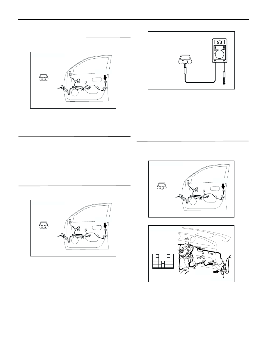
Step 1. Connector check: E-18 door lock key 
cylinder switch (RH) connector

Q: Is the check result normal?

YES : 

Go to Step 2.

NO : 

Repair the defective connector.

Step 2. Check the door lock key cylinder switch 
(RH).

Refer to GROUP 42 

 Door 

P.42-35

.

Q: Is the check result normal?

YES : 

Go to Step 3.

NO : 

Replace the door lock key cylinder switch 
(RH).

Step 3. Measure the resistance at the E-18 door 
lock key cylinder switch (RH) connector.

(1) Disconnect the connector, and measure at the 

wiring harness side.

(2) Resistance between E-18 door lock key cylinder 

switch (RH) connector terminal No. 2 and body 
earth

OK: 2 

 or less

Q: Is the check result normal?

YES : 

Go to Step 5.

NO : 

Go to Step 4.

Step 4. Check the wiring harness between E-18 
door lock key cylinder switch (RH) connector 
terminal No. 2 and body earth.

NOTE: 

Prior to the wiring harness inspection, check 
intermediate connector C-15, and repair if necessary.

Check the earth wires for open circuit.

AC301412

Connector: E-18

Harness side

E-18(B)

AD

3

1

2

AC301412

Connector: E-18

Harness side

E-18(B)

AD

3

1

2

AC301541BL

Connector E-18
(Harness side)

3

1

2

AC301412

Connector: E-18

Harness side

E-18(B)

AD

3

1

2

AC301397

Connector: C-15

AD

C-15(GR)

13

3

7

16

19

15

14

18

17

12

6

4

8

1

9

11

10

5

2

INPUT SIGNAL PROCEDURES

SMART WIRING SYSTEM (SWS) NOT USING SWS MONITOR

54B-382

Q: Is the check result normal?

YES : 

Intermittent malfunction. (Refer to GROUP 

00 

 How to Cope with Intermittent 

Malfunction 

P.00-6

).)

NO : 

Repair the wiring harness.

Step 5. Connector check: C-220 ETACS-ECU 
connector

Q: Is the check result normal?

YES : 

Go to Step 6.

NO : 

Repair the defective connector.

Step 6. Check the wiring harness from E-18 door 
lock key cylinder switch (RH) connector terminal 
Nos. 1 and 3 to C-220 ETACS-ECU connector 
terminal Nos. 28 and 27.

NOTE: 

Prior to the wiring harness inspection, check 
intermediate connector C-15, and repair if necessary.

Check the input line for open circuit.

Q: Is the check result normal?

YES : 

Go to Step 7.

NO : 

Repair the wiring harness.

AC210476

Connector: C-220

Junction block (Rear view)

AF

Harness side

28

37

43

29

44

38

23

32

41

24

25

26

27

34

42

3635

33

21

22

30

39

40

31

AC210476

Connector: C-220

Junction block (Rear view)

AF

Harness side

28

37

43

29

44

38

23

32

41

24

25

26

27

34

42

3635

33

21

22

30

39

40

31

AC301412

Connector: E-18

Harness side

E-18(B)

AD

3

1

2

AC301397

Connector: C-15

AD

C-15(GR)

13

3

7

16

19

15

14

18

17

12

6

4

8

1

9

11

10

5

2

INPUT SIGNAL PROCEDURES

SMART WIRING SYSTEM (SWS) NOT USING SWS MONITOR

54B-383

Step 7. Retest the system.

Check that the passenger's door lock key cylinder 
switch signal is received normally.

Q: Is the check result normal?

YES : 

Intermittent malfunction. (Refer to GROUP 

00 

 How to Cope with Intermittent 

Malfunction 

P.00-6

).)

NO : 

Replace the ETACS-ECU.

INSPECTION PROCEDURE N-18: The front passenger’s door lock key cylinder switch signal is not 
detected. <R.H. drive vehicles>

CAUTION

Whenever the ECU is replaced, ensure that the 
input signal circuit is normal.

COMMENTS ON TROUBLE SYMPTOM
Input signal from the front passenger's door lock key 
cylinder switch is used to operate the central door 
locking function. If the signal is abnormal, the central 
door locking function will not work normally.

POSSIBLE CAUSES

Malfunction of the front passenger's door lock key 
cylinder switch

Malfunction of the ETACS-ECU

Damaged harness wires and connectors

DOOR LOCK
KEY CYLINDER
SWITCH (LH)

ETACS-ECU

Wire colour code
B : Black     LG : Light green     G : Green     L : Blue     W : White     Y : Yellow     SB : Sky blue
BR : Brown     O : Orange     GR : Gray     R : Red     P : Pink     V : Violet   

Door Lock Key Cylinder Switch Input Circuit <RHD>

INPUT SIGNAL PROCEDURES

SMART WIRING SYSTEM (SWS) NOT USING SWS MONITOR

54B-384

DIAGNOSTIC PROCEDURE

Step 1. Connector check: E-04 door lock key 
cylinder switch (LH) connector

Q: Is the check result normal?

YES : 

Go to Step 2.

NO : 

Repair the defective connector.

Step 2. Check the door lock key cylinder switch 
(LH).

Refer to GROUP 42 

 Door 

P.42-35

.

Q: Is the check result normal?

YES : 

Go to Step 3.

NO : 

Replace the door lock key cylinder switch 
(LH).

Step 3. Measure the resistance at the E-04 door 
lock key cylinder switch (LH) connector.

(1) Disconnect the connector, and measure at the 

wiring harness side.

(2) Resistance between E-04 door lock key cylinder 

switch (LH) connector terminal No. 2 and body 
earth

OK: 2 

 or less

Q: Is the check result normal?

YES : 

Go to Step 5.

NO : 

Go to Step 4.

Step 4. Check the wiring harness between E-04 
door lock key cylinder switch (LH) connector 
terminal No. 2 and body earth.

NOTE: 

Prior to the wiring harness inspection, check 
intermediate connector C-34, and repair if necessary.

Check the earth wires for open circuit.

AC308805

Connector: E-04
<RHD>

Harness side

AB

3

1

2

E-04(B)

AC308805

Connector: E-04
<RHD>

Harness side

AB

3

1

2

E-04(B)

AC301541FQ

Connector E-04
(Harness side)

3

1

2

AC308805

Connector: E-04
<RHD>

Harness side

AB

3

1

2

E-04(B)

AC308735

Connector: C-34
<RHD>

AG

C-34(GR)

13

3

7

16

19

15

14

18

17

12

6

4

8

1

9

11

10

5

2


Content   ..  521  522  523  524   ..