Mitsubishi Outlander (2003+). Manual - part 500


  Index      Mitsubishi     Mitsubishi Outlander - service repair manual 2003 year


Search            


Content   ..  498  499  500  501   ..


Mitsubishi Outlander (2003+). Manual - part 500


SYMPTOM PROCEDURES

SMART WIRING SYSTEM (SWS) NOT USING SWS MONITOR

54B-289

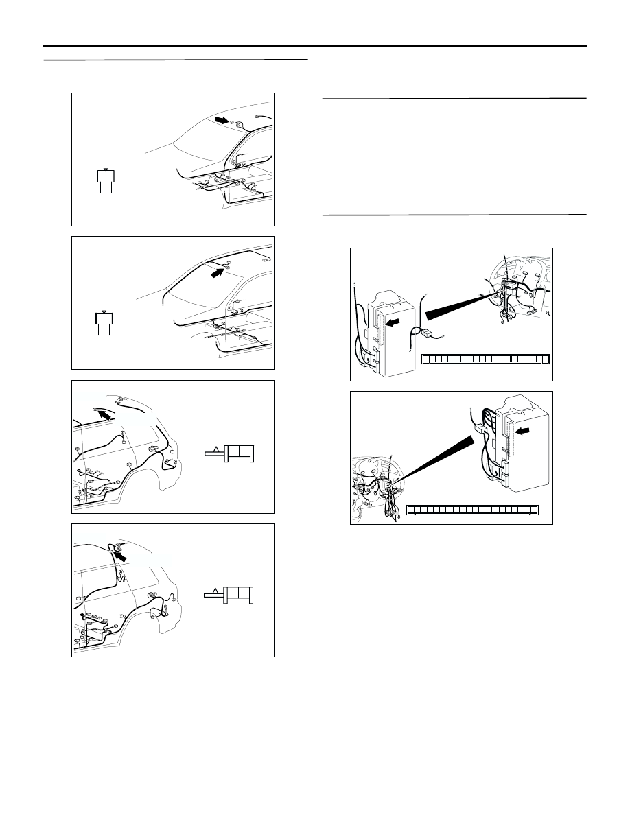
Step 4. Connector check: D-05 front room lamp 
connector, D-11 rear room lamp connector

Q: Is the check result normal?

YES : 

Go to Step 5.

NO : 

Repair the defective connector.

Step 5. Check the bulbs of the front or rear room 
lamps.

Check that the front or rear room lamp bulbs are not 
burned out.

Q: Is the check result normal?

YES : 

Go to Step 6.

NO : 

Replace the front or rear room lamp bulb.

Step 6. Connector check: C-217 ETACS-ECU 
connector

Q: Is the check result normal?

YES : 

Go to Step 7.

NO : 

Repair the defective connector.

AC308781

Connector: D-05

2

1

Harness side

AF

<LHD>

AC308785

Connector: D-05

2

1

Harness side

AE

<RHD>

AC308783

Connector: D-11

AE

Harness side

2 1

D-11(GR)

<LHD>

AC308787

Connector: D-11

AD

Harness side

2 1

D-11(GR)

<RHD>

AC308722

Connector: C-217

Junction block (Rear view)

Junction block side

AD

3

1

2

14

4

5

7 6

8

1110 9

1312

17

15

16

18

19

20

<LHD>

AC308776

Connector: C-217

Junction block (Rear view)

Junction block side

AC

3

1

2

14

4

5

7 6

8

1110 9

1312

17

15

16

18

19

20

<RHD>

SYMPTOM PROCEDURES

SMART WIRING SYSTEM (SWS) NOT USING SWS MONITOR

54B-290

Step 7. Check the wiring harness from C-217 
ETACS-ECU connector terminal Nos. 5 and 6 to 
D-05 front room lamp connector terminal Nos. 2 
and 1.

NOTE: 

Prior to the wiring harness inspection, check junction 
block connector C-210, and repair if necessary.

Q: Is the check result normal?

YES : 

Go to Step 8.

NO : 

Repair the wiring harness.

AC308722

Connector: C-217

Junction block (Rear view)

Junction block side

AD

3

1

2

14

4

5

7 6

8

1110 9

1312

17

15

16

18

19

20

<LHD>

AC308776

Connector: C-217

Junction block (Rear view)

Junction block side

AC

3

1

2

14

4

5

7 6

8

1110 9

1312

17

15

16

18

19

20

<RHD>

AC308781

Connector: D-05

2

1

Harness side

AF

<LHD>

AC308785

Connector: D-05

2

1

Harness side

AE

<RHD>

AC308720

Connector: C-210

Harness side

AK

3

1

2

Junction block (Front view)

<LHD>

AC308772

Connector: C-210

Harness side

AJ

3

1

2

Junction block (Front view)

<RHD>

SYMPTOM PROCEDURES

SMART WIRING SYSTEM (SWS) NOT USING SWS MONITOR

54B-291

Step 8. Check the wiring harness from C-217 
ETACS-ECU connector terminal Nos. 5 and 6 to 
D-11 rear room lamp connector terminal Nos. 2 
and 1.

NOTE: 

Prior to the wiring harness inspection, check junction 
block connector C-210, and repair if necessary.

Q: Is the check result normal?

YES : 

Go to Step 9.

NO : 

Repair the wiring harness.

Step 9. Retest the system.

Check that the front or rear room lamp illuminates 
and extinguishes normally.

Q: Is the check result normal?

YES : 

The trouble can be an intermittent 

malfunction (Refer to GROUP 00 

 How to 

Cope with Intermittent Malfunction 

P.00-6

).

NO : 

Replace the ETACS-ECU.

AC308722

Connector: C-217

Junction block (Rear view)

Junction block side

AD

3

1

2

14

4

5

7 6

8

1110 9

1312

17

15

16

18

19

20

<LHD>

AC308776

Connector: C-217

Junction block (Rear view)

Junction block side

AC

3

1

2

14

4

5

7 6

8

1110 9

1312

17

15

16

18

19

20

<RHD>

AC308783

Connector: D-11

AE

Harness side

2 1

D-11(GR)

<LHD>

AC308787

Connector: D-11

AD

Harness side

2 1

D-11(GR)

<RHD>

AC308720

Connector: C-210

Harness side

AK

3

1

2

Junction block (Front view)

<LHD>

AC308772

Connector: C-210

Harness side

AJ

3

1

2

Junction block (Front view)

<RHD>

SYMPTOM PROCEDURES

SMART WIRING SYSTEM (SWS) NOT USING SWS MONITOR

54B-292

INSPECTION PROCEDURE M-3: Interior lamp automatic shutoff function does not work normally. 
<Vehicles with keyless entry system>

CAUTION

Whenever the ECU is replaced, ensure that the 
input and output signal circuits are normal.

COMMENTS ON TROUBLE SYMPTOM
The ETACS-ECU operates the interior lamp 
automatic-shutdown function in accordance with the 
input signals below.

Ignition switch (ACC)

Ignition switch (IG1)

Driver's door switch

All of the door switches

Interior lamp loaded signal

If this function does not work normally, these input 
signal circuit(s) or the ETACS-ECU may be 
defective. Note that this function can be 
disabled/enabled by the adjustment function (default 
setting; enabled).

POSSIBLE CAUSES

Malfunction of the door switches

Malfunction of the room lamp

Malfunction of the ETACS-ECU

Damaged harness wires and connectors

DIAGNOSTIC PROCEDURE

Step 1. Check the adjustment function.

Check that the interior lamp automatic-shutdown 
function has been enabled by using the adjustment 
function.

Q: Is the check result normal?

YES : 

Go to Step 2.

NO : 

Enable the interior lamp 
automatic-shutdown function by using the 
adjustment function. Refer to 

P.54B-393

.

INPUT SIGNAL

COMBINATION 
METER

· FRONT ROOM LAMP
· REAR ROOM LAMP

KEEP RELAY

INTERIOR 
LAMP CUT 
BACK-UP 
CIRCUIT

LOAD 
DETERMINATION 
CIRCUIT

· ALL DOOR
  SWITCH
· FRONT DOOR
  SWITCH
· IGNITION
  SWITCH (ACC)
· IGNITION
  SWITCH (IG1)
· INTERIOR LAMP
  LOADED SIGNAL

ETACS-ECU

BATTERY

Interior Lamp Automatic Shut-off Function Circuit


Content   ..  498  499  500  501   ..