Mitsubishi Outlander (2003+). Manual - part 499
SYMPTOM PROCEDURES
SMART WIRING SYSTEM (SWS) NOT USING SWS MONITOR
54B-285
NOTE:
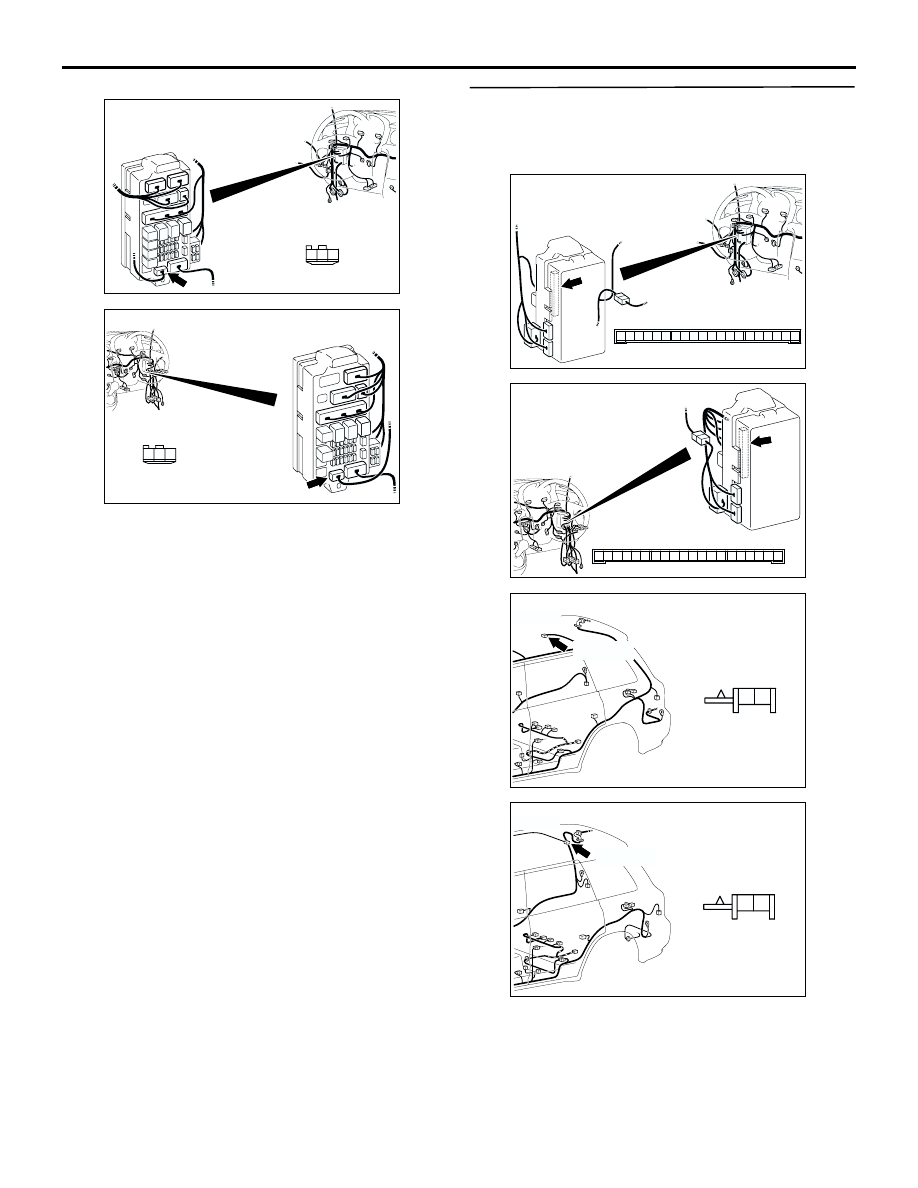
Prior to the wiring harness inspection, check junction
block connector C-210, and repair if necessary.
Q: Is the check result normal?
YES :
Go to Step 7.
NO :
Repair the wiring harness.
Step 7. Check the wiring harness from C-217
ETACS-ECU connector terminal Nos. 5 and 6 to
D-11 rear room lamp connector terminal Nos. 2
and 1.
AC308720
Connector: C-210
Harness side
AK
3
1
2
Junction block (Front view)
<LHD>
AC308772
Connector: C-210
Harness side
AJ
3
1
2
Junction block (Front view)
<RHD>
AC308722
Connector: C-217
Junction block (Rear view)
Junction block side
AD
3
1
2
14
4
5
7 6
8
1110 9
1312
17
15
16
18
19
20
<LHD>
AC308776
Connector: C-217
Junction block (Rear view)
Junction block side
AC
3
1
2
14
4
5
7 6
8
1110 9
1312
17
15
16
18
19
20
<RHD>
AC308783
Connector: D-11
AE
Harness side
2 1
D-11(GR)
<LHD>
AC308787
Connector: D-11
AD
Harness side
2 1
D-11(GR)
<RHD>