Mitsubishi Outlander (2003+). Manual - part 445
SYMPTOM PROCEDURES
SMART WIRING SYSTEM (SWS) NOT USING SWS MONITOR
54B-69
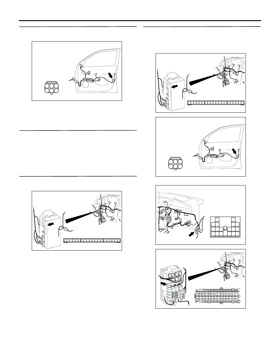
Step 6. Connector check: E-25 door lock actuator
(front: RH) connector
Q: Is the check result normal?
YES :
Go to Step 7.
NO :
Repair the defective connector.
Step 7. Check the door lock actuator (front: RH).
Check that the door lock actuator (front: RH) works
normally. Refer to GROUP 42
−
Door
.
Q: Is the check result normal?
YES :
Go to Step 8.
NO :
Replace the door lock actuator (front: RH).
Step 8. Connector check: C-217 ETACS-ECU
connector
Q: Is the check result normal?
YES :
Go to Step 9.
NO :
Repair the defective connector.
Step 9. Check the wiring harness from C-217
ETACS-ECU connector terminal Nos. 12 and 13 to
E-25 door lock actuator (front: RH) connector
terminal Nos. 4 and 6.
NOTE:
Prior to the wiring harness inspection, check
intermediate connector C-15 and junction block
connector C-205, and repair if necessary.
•
Check the input and output lines for open circuit.
AC308793AC
Connector: E-25
Harness side
E-25(B)
5
6
4
2
3
1
<LHD>
AC308722
Connector: C-217
Junction block (Rear view)
Junction block side
AD
3
1
2
14
4
5
7 6
8
1110 9
1312
17
15
16
18
19
20
<LHD>
AC308722
Connector: C-217
Junction block (Rear view)
Junction block side
AD
3
1
2
14
4
5
7 6
8
1110 9
1312
17
15
16
18
19
20
<LHD>
AC308793AC
Connector: E-25
Harness side
E-25(B)
5
6
4
2
3
1
<LHD>
AC308718
Connector: C-15 <LHD>
AG
C-15(GR)
13
3
7
16
19
15
14
18
17
12
6
4
8
1
9
11
10
5
2
AC308720
Connector: C-205
Harness side
AC
Junction block (Front view)
<LHD>