Mitsubishi Outlander (2003+). Manual - part 415


  Index      Mitsubishi     Mitsubishi Outlander - service repair manual 2003 year


Search            


Content   ..  413  414  415  416   ..


Mitsubishi Outlander (2003+). Manual - part 415


COMBINATION METER ASSEMBLY

CHASSIS ELECTRICAL

54A-55

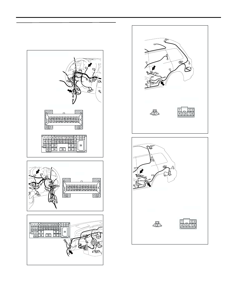
STEP 3. Check the wiring harness between 
combination meter connector C-04 (terminal 43) 
and fuel gauge unit connector D-15 (terminal 1) 
<2WD> or fuel pump and gauge unit (main) 
connector D-16 (terminal 2) <4WD>.

NOTE: 

Prior to the wiring harness inspection, check fuel 
gauge unit (sub) connector D-12, intermediate 
connector C-117, D-24, and repair if necessary.

AC308717

AR

C-04

C-117

Connectors: C-04, C-117 <LHD>

C-04 harness side

C-117

AC308769

Connector: C-04 <RHD>

C-04 harness side

AS

AC308735

AU

C-117

Connector: C-117 <RHD>

AC301594

Connectors: D-12, D-24 <LHD>

AD

D-12

D-24

D-12 
harness side

D-24

AC308788

Connectors: D-12, D-24 <RHD>

AE

D-12

D-24

D-12 
harness side

D-24

COMBINATION METER ASSEMBLY

CHASSIS ELECTRICAL

54A-56

Q: Is the wiring harness between combination meter 

connector C-04 (terminal 43) and fuel gauge unit 
connector D-15 (terminal 1) <2WD> or fuel pump 
and gauge unit (main) connector D-16 (terminal 2) 
<4WD> in good condition?

YES : 

Go to Step 4.

NO : 

Repair or replace the damaged 
component(s). Then go to Step 4.

STEP 4. Retest the system.

Q: Is the fuel gauge normal?

YES : 

The procedure is complete. (If no 

malfunctions are found in all steps, an 
intermittent malfunction is suspected. Refer 
to GROUP 00, How to Use 
Troubleshooting/Inspection Service 
Points-How to Cope with Intermittent 
Malfunction 

P.00-6

).

NO : 

Go to Step 5.

STEP 5. Connector check: Fuel gauge unit 
connector D-15 <2WD> or fuel pump and gauge 
unit (main) D-16 <4WD>

Q: Is fuel gauge unit connector D-15 <2WD> or fuel 

pump and gauge unit (main) D-16 <4WD> in good 
condition?

YES : 

Go to Step 6.

NO : 

Repair or replace the damaged 
component(s). 

STEP 6. Check the wiring harness between fuel 
gauge unit connector D-15 (terminal 2) <2WD> 
and fuel pump and gauge unit connector D-16 
(terminal 1) <4WD> and earth.

NOTE: 

Prior to the wiring harness inspection, check 
intermediate connectors D-24, and repair if 
necessary.

AC308783

Connectors: D-15<2WD>, D-16<4WD>
<LHD>

AF

D-15 (B)

D-16 (GR)

D-15<2WD>

D-16<4WD>

harness side

harness side

3 2 1

1

2

3

4

5

AC308787

Connector: D-16 <4WD>
<RHD>

AF

D-16 (GR)

harness side

1

2

3

4

5

AC308783

Connectors: D-15<2WD>, D-16<4WD>
<LHD>

AF

D-15 (B)

D-16 (GR)

D-15<2WD>

D-16<4WD>

harness side

harness side

3 2 1

1

2

3

4

5

AC308787

Connector: D-16 <4WD>
<RHD>

AF

D-16 (GR)

harness side

1

2

3

4

5

AC301595

Connector: D-24 <LHD>

AC

D-24

AC308787

Connector: D-24 <RHD>

AG

D-24

COMBINATION METER ASSEMBLY

CHASSIS ELECTRICAL

54A-57

Q: Is the wiring harness between fuel gauge unit 

connector D-15 (terminal 2) <2WD> and fuel pump 
and gauge unit connector D-16 (terminal 1) <4WD> 
and earth in good condition?

YES : 

Go to Step 7.

NO : 

Repair or replace the damaged 
component(s).

STEP 7. Retest the system.

Q: Is the fuel gauge normal?

YES : 

The procedure is complete. (If no 

malfunctions are found in all steps, an 
intermittent malfunction is suspected. Refer 
to GROUP 00, How to Use 
Troubleshooting/Inspection Service 
Points-How to Cope with Intermittent 
Malfunction 

P.00-6

).

NO : 

Carry out the troubleshooting again.

STEP 8. Check the fuel gauge circuit.
(1) Disconnect D-15 <2WD> fuel gauge unit 

connector or D-16 <4WD> fuel pump and gauge 
unit (main) connector.

(2) Connect a test lamp (12 V 

 3.4 W) via special 

tool test harness (MB991219) between the wiring 
harness connector terminals 1 and 2.

(3) Turn the ignition switch to the "ON" position.

Q: Does the fuel gauge in the combination meter 

fluctuate about half of it full scale?

YES : 

Replace the fuel gauge unit.

NO : 

Go to Step 9.

STEP 9. Retest the system.

Q: Is the fuel gauge normal?

YES : 

The procedure is complete. (If no 

malfunctions are found in all steps, an 
intermittent malfunction is suspected. Refer 
to GROUP 00, How to Use 
Troubleshooting/Inspection Service 
Points-How to Cope with Intermittent 
Malfunction 

P.00-6

).

NO : 

Replace combination meter. 

AC103414

AC211647

3 2 1

1

2

3

4

5

Test lamp
(12 V - 3.4 W)

MB991219

D-15 <2WD>

Component side

D-16 <4WD>

Component side

AB

COMBINATION METER ASSEMBLY

CHASSIS ELECTRICAL

54A-58

INSPECTION PROCEDURE 5: Engine Coolant Temperature Gauge does not Work. (the other meters 
work.) 

TECHNICAL DESCRIPTION (COMMENT)
If only the engine coolant temperature gauge does 
not operate, the combination meter, the wiring 
harness or its connector may be defective.

TROUBLESHOOTING HINTS

Malfunction of the engine coolant temperature 
gauge unit

The wiring harness or connectors may have 
loose, corroded, or damaged terminals, or 
terminals pushed back in the connector.

Malfunction of the combination meter.

DIAGNOSIS PROCEDURE 

STEP 1. Check the engine coolant temperature 
gauge circuit.
(1) Disconnect the B-109 engine coolant 

temperature gauge unit connector.

(2) Connect a test lamp (12 V 

 3.4 W to 12 V 

 7.0 

W) to the wiring harness side connector.

(3) Ignition switch: ON

Q: Does the test lamp illuminate?

YES : 

Go to Step 5.

NO : 

Go to Step 2.

T/GA

Wire colour code
B : Black     LG : Light green     G : Green     L : Blue     W : White     Y : Yellow     SB : Sky blue
BR : Brown     O : Orange     GR : Gray     R : Red     P : Pink     V : Violet   

COMBINATION 
METER

CONTROL 
CIRCUIT

ENGINE COOLANT 
TEMPERATURE 
GAUGE UNIT

Engine Coolant Temperature Gauge Circuit

AC102026AD

Connector

Earth

Test lamp
(12 V 3.4 W - 7.0 W)


Content   ..  413  414  415  416   ..