Mitsubishi Outlander (2003+). Manual - part 413


  Index      Mitsubishi     Mitsubishi Outlander - service repair manual 2003 year


Search            


Content   ..  411  412  413  414   ..


Mitsubishi Outlander (2003+). Manual - part 413


COMBINATION METER ASSEMBLY

CHASSIS ELECTRICAL

54A-47

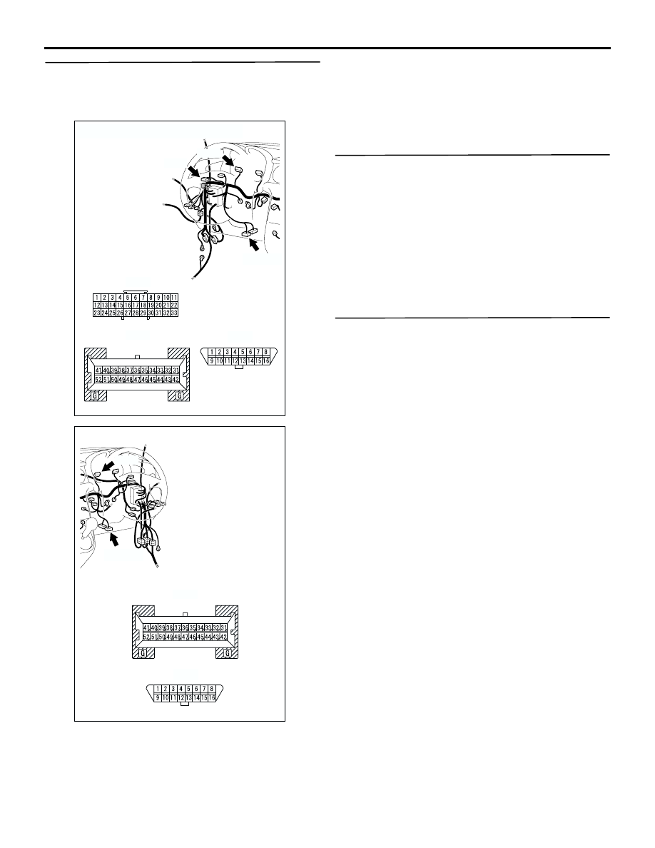
STEP 3. Check the wiring harness between 
combination meter connector C-04 (terminal 46) 
and diagnosis connector C-24 (terminal 14).
NOTE: 

Prior to the wiring harness inspection, joint connector 
C-02 <LHD>, and repair if necessary.

Q: Is the wiring harness between combination meter 

connector C-04 (terminal 46) and diagnosis 
connector C-24 (terminal 14) in good condition?

YES : 

Go to Step 4

NO : 

Repair or replace the damage 
component(s).

STEP 4. Retest the system.

Q: Is the speedometer normal?

YES : 

The procedure is complete. (If no 

malfunctions are found in all steps, an 
intermittent malfunction is suspected. Refer 
to GROUP 00, How to Use 
Troubleshooting/Inspection Service 
Points-How to Cope with Intermittent 
Malfunction 

P.00-6

).

NO : 

Replace the combination meter assembly.

STEP 5. Check whether the diagnosis code is 
reset.

Q: Is the MPI-related diagnosis code set?

YES : 

Refer to GROUP GROUP 13B 


Troubleshooting 

P.13B-20

.

NO : 

Go to Step 6

AC308717

Connectors: C-02, C-04, C-24 <LHD>

C-24(B)

C-04

C-04 harness side

C-24

AQ

C-02

C-02

AC308770

Connectors: C-04, C-24 <RHD>

C-24(B)

C-04

C-04 harness side

C-24

AG

COMBINATION METER ASSEMBLY

CHASSIS ELECTRICAL

54A-48

STEP6. Connector check: Joint connector C-02 
<LHD> and engine-A/T-ECU connector C-141

Q:  Is joint connector C-02 <LHD> and 

engine-A/T-ECU connector C-141 in good 
condition?

YES : 

Go to Step 7

NO : 

Repair or replace the damage 
component(s).

STEP 7. Check the wiring harness between joint 
connector C-02 <LHD> (terminal 25) and 
engine-A/T-ECU connector C-141 (terminal 79).

AC308716

Connector: C-02

AP

C-02

AC308718

AN

C-141(GR)

Connector: C-141 <LHD>

Harness side

C-141

AC308735

AS

C-141(GR)

Connector: C-141 <RHD>

Harness side

C-141

AC308716

Connector: C-02

AP

C-02

AC308718

AN

C-141(GR)

Connector: C-141 <LHD>

Harness side

C-141

AC308735

AS

C-141(GR)

Connector: C-141 <RHD>

Harness side

C-141

COMBINATION METER ASSEMBLY

CHASSIS ELECTRICAL

54A-49

NOTE: 

Prior to the wiring harness inspection, check 
intermediate connectors C-105 and repair if 
necessary.

Q: Is the wiring harness between joint connector C-02 

<LHD> (terminal 25) and engine-A/T-ECU 
connector C-141 (terminal 79) in good condition?

YES : 

Go to Step 8

NO : 

Repair or replace the damage 
component(s).

STEP 8. Retest the system.

Q: Is the speedometer normal?

YES : 

The procedure is complete. (If no 

malfunctions are found in all steps, an 
intermittent malfunction is suspected. Refer 
to GROUP 00, How to Use 
Troubleshooting/Inspection Service 
Points-How to Cope with Intermittent 
Malfunction 

P.00-6

).

NO : 

Go to Step 9.

STEP 9. Pulse check

Use the MUT-II/III or a voltmeter to check that the 
output shaft speed signal is received.

OK: The MUT-II/III sounds or the voltmeter 
needle fluctuates.

Q: Is the check result normal?

YES : 

Replace the combination meter assembly.

NO : 

Replace the engine-A/T-ECU.

AC308718

AO

Connector: C-105 <LHD>

C-105

AC308735

AT

Connector: C-105 <RHD>

C-105

System switch

Check conditions

Output shaft speed 
signal

When the vehicle speed 
has reached 10 km/h or 
more

COMBINATION METER ASSEMBLY

CHASSIS ELECTRICAL

54A-50

INSPECTION PROCEDURE 3: Tachometer does not work (the other meters work.) 

TECHNICAL DESCRIPTION (COMMENT)
Ignition signal may not be received from the 
engine-ECU or engine-A/T-ECU, or the combination 
meter assembly, the wiring harness, or the 
connector(s) may be defective.

TROUBLESHOOTING HINTS

Malfunction of the combination meter assembly

The wiring harness or connectors may have 
loose, corroded, or damaged terminals, or 
terminals pushed back in the connector.

DIAGNOSIS PROCEDURE 

STEP 1. Check whether the diagnosis code is 
reset.

Q: Is the MPI-related diagnosis code set?

Code No.P0300 is set : 

Refer to GROUP 13A 


Troubleshooting 

P.13A-111

, GROUP 13B 


Troubleshooting 

P.13B-152

.

NO : 

Go to Step 2

COMBINATION 
METER

CONTROL 
CIRCUIT

TACHO

Wire colour code
B : Black     LG : Light green     G : Green     L : Blue     W : White     Y : Yellow     SB : Sky blue
BR : Brown     O : Orange     GR : Gray     R : Red     P : Pink     V : Violet   

ENGINE-ECU OR
ENGINE-A/T-ECU

NOTE

: 4G63
: 4G69

Tachometer Circuit


Content   ..  411  412  413  414   ..