Mitsubishi Outlander (2003+). Manual - part 412


  Index      Mitsubishi     Mitsubishi Outlander - service repair manual 2003 year


Search            


Content   ..  410  411  412  413   ..


Mitsubishi Outlander (2003+). Manual - part 412


COMBINATION METER ASSEMBLY

CHASSIS ELECTRICAL

54A-43

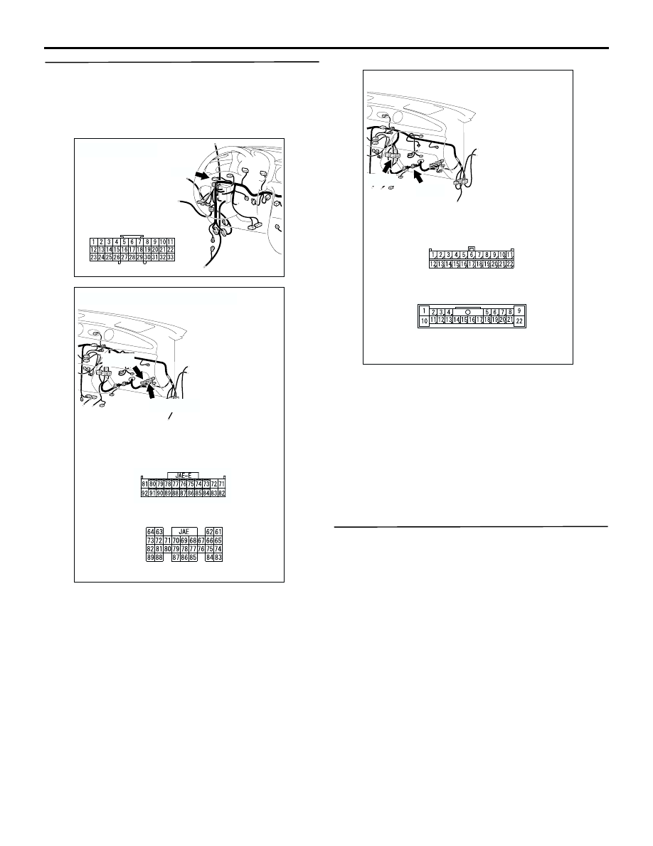
STEP 7. Check the wiring harness between joint 
connector C-02 (terminal 25) and engine-ECU 
<2000> connector C-137 (terminal 86) or 
engine-ECU <2400> connector C-141 (terminal 
79).

NOTE: 

Prior to the wiring harness inspection, check 
intermediate connectors C-105, joint connectors 
C-16 <2000> and repair if necessary.

Q: Is the wiring harness between joint connector C-02 

(terminal 25) and engine-ECU <2000> connector 
C-137 (terminal 86) or engine-ECU <2400> 
connector C-141 (terminal 79) in good condition?

YES : 

Go to Step 8

NO : 

Repair or replace the damage 
component(s).

STEP 8. Retest the system.

Q: Is the speedometer normal?

YES : 

The procedure is complete. (If no 

malfunctions are found in all steps, an 
intermittent malfunction is suspected. Refer 
to GROUP 00, How to Use 
Troubleshooting/Inspection Service 
Points-How to Cope with Intermittent 
Malfunction 

P.00-6

).

NO : 

Go to Step 9.

AC308716

Connector: C-02

AP

C-02

AC308719

AG

C-141(GR)

Connectors: C-137 <2000>, C-141 <2400>

Harness side

C-137

C-141

C-137

AC308719

AF

Connectors: C-16 <2000>, C-105

C-16 (L)

C-16

C-105

C-105

COMBINATION METER ASSEMBLY

CHASSIS ELECTRICAL

54A-44

STEP 9. Pulse check

Use the MUT-II/III or a voltmeter to check that the 
vehicle speed signal is received.

OK: The MUT-II/III sounds or the voltmeter 
needle fluctuates.

Q: Is the check result normal?

YES : 

Replace the combination meter assembly.

NO : 

Replace the engine-ECU.

System switch

Check conditions

Vehicle speed signal

When the vehicle speed 
has reached 10 km/h or 
more

COMBINATION METER ASSEMBLY

CHASSIS ELECTRICAL

54A-45

INSPECTION PROCEDURE 2: Speedometer does not work (the other meters work.)  <A/T>

TECHNICAL DESCRIPTION (COMMENT)
The engine-A/T-ECU and its associated 
components, the combination meter assembly, the 
wiring harness, or the connector(s) may be defective.

TROUBLESHOOTING HINTS

Malfunction of the output shaft speed sensor

Malfunction of the engine-ECU

Malfunction of the combination meter assembly

The wiring harness or connectors may have 
loose, corroded, or damaged terminals, or 
terminals pushed back in the connector.

ENGINE-A/T-ECU

Wire colour code
B : Black     LG : Light green     G : Green     L : Blue     W : White     Y : Yellow     SB : Sky blue
BR : Brown     O : Orange     GR : Gray     R : Red     P : Pink     V : Violet   

IGNITION 
SWITCH (IG1)

COMBINATION 
METER

OUTPUT 
SHAFT
SPEED 
SENSOR

DIAGNOSIS 
CONNECTOR

LHD

RHD

<RHD>

FRONT SIDE

DIAGNOSIS 
CONNECTOR

FRONT SIDE

CONTROL 
CIRCUIT

SPEED

Speedometer Circuit <A/T>

COMBINATION METER ASSEMBLY

CHASSIS ELECTRICAL

54A-46

DIAGNOSIS PROCEDURE 

STEP 1. Check the speedometer.

(1) Connect the MUT-II/III to the diagnosis connector.
(2) Use the MUT-II/III to enter simulated vehicle 

speed.

Q: Does the speedometer show that simulated vehicle 

speed?

YES : 

Go to Step 5

NO : 

Go to Step 2

STEP 2. Connector check: Combination meter 
connector C-04 and diagnosis connector C-24

Q:  Is combination meter connector C-04 and 

diagnosis connector C-24 in good condition?

YES : 

Go to Step 3

NO : 

Repair or replace the damage 
component(s).

AC300830

Steering shaft

MUT-II

AC

<Using the MUT-II>

AC308915 AC

MB991911

16-PIN

MB991827

MB991824 

<Using the MUT-III>

AC308717

Connectors: C-04, C-24 <LHD>

C-24(B)

C-04

C-04 harness side

C-24

AP

AC308770

Connectors: C-04, C-24 <RHD>

C-24(B)

C-04

C-04 harness side

C-24

AG


Content   ..  410  411  412  413   ..