Mitsubishi Outlander (2003+). Manual - part 354


  Index      Mitsubishi     Mitsubishi Outlander - service repair manual 2003 year


Search            


Content   ..  352  353  354  355   ..


Mitsubishi Outlander (2003+). Manual - part 354


TROUBLESHOOTING

SUPPLEMENTAL RESTRAINT SYSTEM (SRS)

52B-15

DIAGNOSIS CODE SET CONDITIONS
These diagnosis codes are set if these is abnormal 
resistance between the input terminals of the front 
impact sensors.

The most likely causes for these codes to be set are 
shown in the table below:

PROBABLE CAUSES

Malfunction of the front impact sensor

Damaged wiring harnesses or connector

Malfunction of the SRS-ECU

DIAGNOSIS PROCEDURE

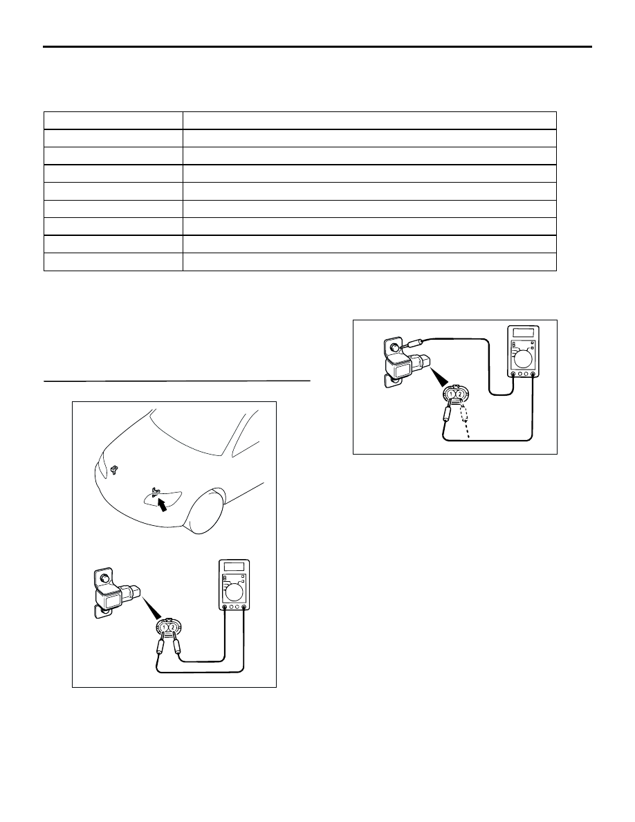
STEP 1. Check the front impact sensor.

(1) Measure the resistance between terminals and 

check whether it is within the standard value.

Standard value: 820 

±

 82 

(2) Check for continuity between the terminal and 

bracket.

OK: No continuity

Q: Does the resistance meet the value above, and is 

there no continuity?
YES : 

Go to Step 2.

NO : 

Replace front impact sensor. Refer to 

P.52B-176

.

Code No.

Trouble causes

1A

Left front impact sensor or its wiring shorted

1B

Left front impact sensor or wiring open circuit

1C

Short to the power supply in the left front impact sensor harness

1D

Short to body earth in the left front impact sensor harness

2A

Right front impact sensor or its wiring shorted

2B

Right front impact sensor or wiring open circuit

2C

Short to the power supply in the right front impact sensor harness

2D

Short to body earth in the right front impact sensor harness

AC201934

AC200633

TROUBLESHOOTING

SUPPLEMENTAL RESTRAINT SYSTEM (SRS)

52B-16

STEP 2. Measure the resistance and voltage at 
SRS-ECU connector C-115.

(1) Disconnect SRS-ECU connector C-115 and 

measure at the harness side (rear side).

CAUTION

Do not insert a test probe into the terminal from 
its front side directly as the connector contact 
pressure may be weakened.
(2) Measure the resistance between terminal 3 and 

terminal 4.

OK: 820 

±

 82 

(3) Measure the resistance between terminal 1 and 

terminal 2.

OK: 820 

±

 82 

(4) Measure the resistance between terminal 1, 2, 3, 

4 and body earth.

OK: 2 M

 or more

(5) Ignition switch: ON position

(6) Measure the voltage between terminal 1, 2, 3, 4 

and body earth.

OK: 0 V

Q: Is the check result normal?

YES : 

Erase the diagnosis code memory, and 

check the diagnosis code. If diagnosis code 
1A, 1B, 1C, 1D, 2A, 2B, 2C or 2D sets, 
replace the SRS-ECU. Refer to 

P.52B-178

Then go to Step  .

NO : 

Go to Step 3.

AC301661AC

Harness side
connector
(front view)

Connector: C-115

SRS-ECU

C-115 (Y)

Center lower
panel

1110 9

1

2

3

1413

12

4

5

6

16

8

15

7

17

18

19

20

1314151617181920

5 6 7 8 9 101112

1 2

3 4

AC300941AB

C-115 Harness side
connector
(rear view)

1314151617181920

5 6 7 8 9 101112

1 2

3 4

AC300942 AB

C-115 Harness side
connector
(rear view)

AC103372

4

1

2

3

5

7

6

8

16

15

14

13

12

11

10

9

20

19

18

17

C-115 Harness side
connector
(rear view)

AH

4

1

2

3

5

7

6

8

16

15

14

13

12

11

10

9

20

19

18

17

AC205526

C-115 Harness side
connector
(rear view)

AE

TROUBLESHOOTING

SUPPLEMENTAL RESTRAINT SYSTEM (SRS)

52B-17

STEP 3. Connector check: SRS-ECU connector 
C-115, front impact sensor (LH) connector A-17, 
intermediate connector C-116, front impact 
sensor (RH) connector A-28 and intermediate 
connector C-14

Q: Is the check result normal?

YES : 

Check the harness wires for open or short 

circuit between SRS-ECU connector C-115 
(terminal No.3 and 4) and front impact 
sensor (LH) connector A-17 (terminal No.1 
and 2), SRS-ECU connector C-115 
(terminal No.1 and 2) and front impact 
sensor (RH) connector A-28 (terminal No.2 
and 1), and repair if necessary. Then go to 
Step 4.

NO : 

Repair or replace it. Then go to Step 4.

AC301661AC

Harness side
connector
(front view)

Connector: C-115

SRS-ECU

C-115 (Y)

Center lower
panel

1110 9

1

2

3

1413

12

4

5

6

16

8

15

7

17

18

19

20

AC301613

Harness side
connector
(front view)

Connector: A-17

AC

A-17 (Y)

2

1

AC301395

<LHD>

AG

9

21

33

35

24

12

3 4

7

8

5 6

39

28

41

30

18

4243

31

1920

32

40

29

1617

38

27

15

37

36

26

14

13

25

2

1

34

23

11

10

22

Connector: C-116

AC308735

AP

9

21

33

35

24

12

3 4

7

8

5 6

39

28

41

30

18

4243

31

1920

32

40

29

1617

38

27

15

37

36

26

14

13

25

2

1

34

23

11

10

22

Connector: C-116
<RHD>

AC210453

Harness side
connector
(front view)

CONNECTOR: A-28

AH

A-28 (Y)

2

1

AC301397

Connector: C-14

AW

9

3

2

1
5 6 7 8

4

10

<LHD>

AC308769

Connector: C-14 <RHD>

AQ

TROUBLESHOOTING

SUPPLEMENTAL RESTRAINT SYSTEM (SRS)

52B-18

STEP 4. Check whether the diagnosis code is 
reset.

Q: Is any of diagnosis code 1A, 1B, 1C, 1D, 2A, 2B, 2C 

or 2D set?

YES : 

Return to Step 1.

NO : 

The procedure is complete (If no 
malfunctions are found in all steps, an 
intermittent malfunction is suspected. Refer 
to GROUP 00 

 How to Use 

Troubleshooting/Inspection Service Points 

P.00-6

).

Code No.11: Front impact sensor short-circuited
Code No.12: One front impact sensor open-circuited
Code No.13: Two front impact sensor open-circuited

OPERATION

When the left and right front impact sensors 
detect a collision, the switches inside the sensors 
turns ON.

SRS-ECU judges how severe a collision is by 
detecting signals from the front impact sensors 
and the front air bag analog G-sensor. If the 
impact is over a predetermined level, the 
SRS-ECU outputs an ignition signal. At this time, 
if the front air bag safing G-sensor is on, the SRS 
air bag will inflate.

MICROCOMPUTER

INTERFACE CIRCUIT

SRS-ECU

FRONT IMPACT 
SENSOR (RH)

FRONT IMPACT 
SENSOR (LH)

Wire colour code
B : Black     LG : Light green
G : Green     L : Blue      
W : White     Y : Yellow
SB : Sky blue     BR : Brown 
O : Orange     GR : Gray  
R : Red     P : Pink     V : Violet       

AC301793AB

Front Impact Sensor Circuit


Content   ..  352  353  354  355   ..