Mitsubishi Outlander (2003+). Manual - part 315


  Index      Mitsubishi     Mitsubishi Outlander - service repair manual 2003 year


Search            


Content   ..  313  314  315  316   ..


Mitsubishi Outlander (2003+). Manual - part 315


DOOR

BODY

42-35

INSTALLATION SERVICE POINTS

>>A<< DOOR CHECK INSTALLATION

Install the door check so that the identification mark 
faces upwards.

>>B<< LOWER SASH INSTALLATION
Securely insert the rear lower sash into the window 
rear sash.

>>C<< DOOR INSIDE HANDLE INSTALLATION

1. Install the inside lock cable to the door inside 

handle as follows:
(1) Install the inner cable end in the inside lock 

cable to the clip in the door inside handle.

(2) Turn the inside lock knob to the door lock 

position.

(3) Install the outer cable end to the door inside 

handle securely.

(4) Install the clip to the inner cable.

2. Install the inside handle rod to the door inside 

handle.

3. Install the door inside handle to the door.

INSPECTION

M1423004700477

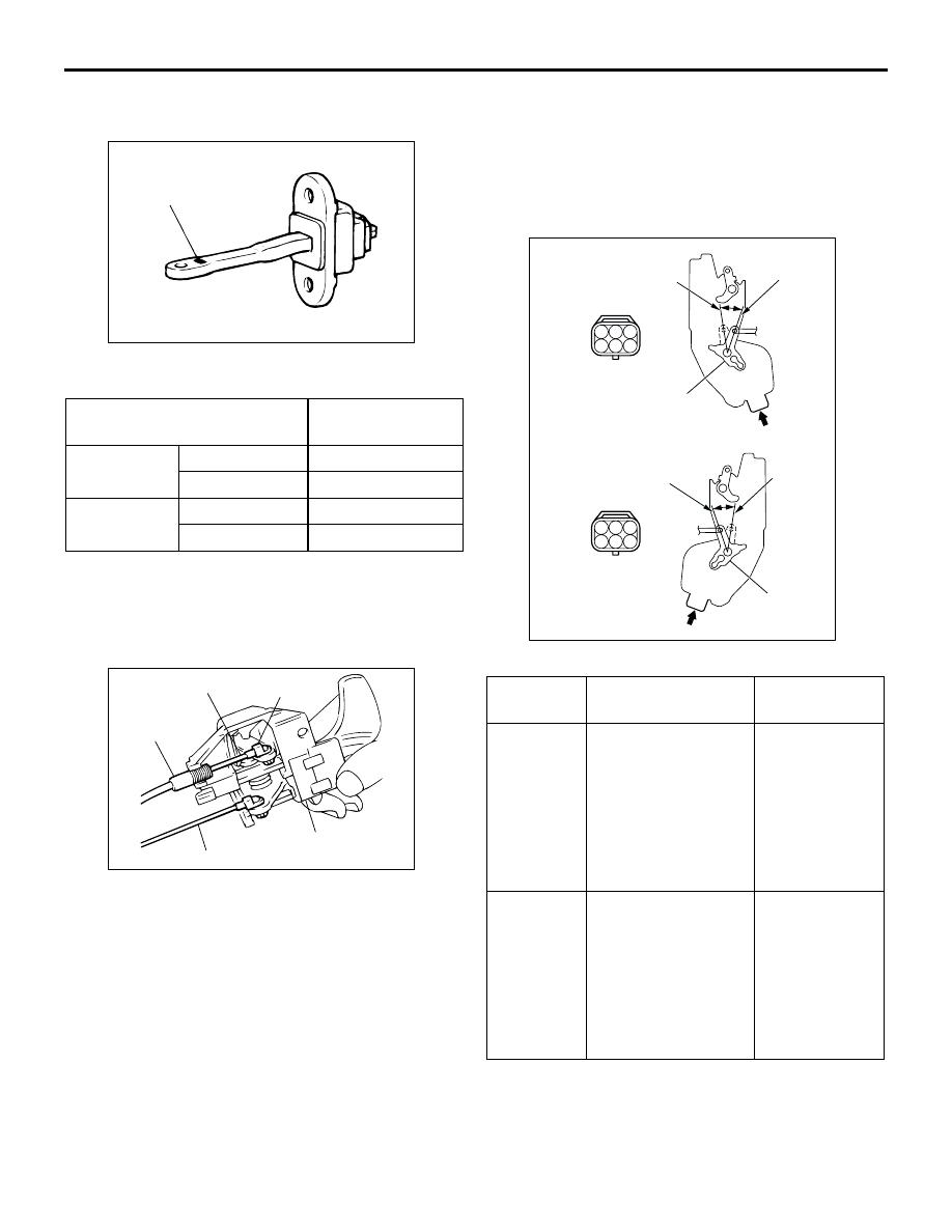
FRONT DOOR LOCK ACTUATOR CHECK

Actuator Operation Check <Left side>

ITEM

IDENTIFICATION 
MARK

Front Door

Left door

39L

Right door

39R

Rear Door

Left door

40L

Right door

40R

ACX00541

Identification mark

AB

AC100404 AB

Clip

Inner cable

Outer cable end

Inside handle rod

Door inside handle

LEVER 
POSITION

BATTERY 
CONNECTION

LEVER 
OPERATION

At the 
"LOCK" 
position

Connect terminal 
No.6 and the 
negative battery  
terminal.

Connect terminal 
No.4 and the 
positive battery  
terminal.

The lever 
moves from the 
"LOCK" 
position to the 
"UNLOCK" 
position.

At the 
"UNLOCK" 
position

Connect terminal 
No.4 and the 
negative battery  
terminal.

Connect terminal 
No.6 and the 
positive battery  
terminal.

The lever 
moves from the 
"UNLOCK" 
position to the 
"LOCK" 
position.

AC005657

1 2 3

4 5 6

1 2 3

4 5 6

Lock

Unlock

View A

View B

Unlock

Lock

B

Front door

<Left side>

<Right side>

AD

A

Lever

Lever

DOOR

BODY

42-36

Actuator Switch Check <Left side (LH drive 
vehicles)>

Actuator Operation Check <Right side>

Actuator Switch Check <Right side (RH drive 
vehicles)>

REAR DOOR LOCK ACTUATOR CHECK

Actuator Operation Check <Left side>

LEVER 
POSITION

TESTER 
CONNECTION

SPECIFIED 
CONDITION

At the "LOCK" 
position

 3

Less than 2 
ohms

At the 
"UNLOCK" 
position

 2

Less than 2 
ohms

LEVER 
POSITION

BATTERY 
CONNECTION

LEVER 
OPERATION

At the 
"LOCK" 
position

Connect terminal 
No.4 and the 
negative battery  
terminal.

Connect terminal 
No.6 and the 
positive battery  
terminal.

The lever 
moves from 
the "LOCK" 
position to the 
"UNLOCK" 
position.

At the 
"UNLOCK" 
position

Connect terminal 
No.6 and the 
negative battery  
terminal.

Connect terminal 
No.4 and the 
positive battery  
terminal.

The lever 
moves from 
the "UNLOCK" 
position to the 
"LOCK" 
position.

LEVER 
POSITION

TESTER 
CONNECTION

SPECIFIED 
CONDITION

At the "LOCK" 
position

 3

Less than 2 
ohms

At the 
"UNLOCK" 
position

 3

Less than 2 
ohms

LEVER 
POSITION

BATTERY 
CONNECTION

LEVER 
OPERATION

At the 
"LOCK" 
position

Connect terminal 
No.3 and the 
negative battery  
terminal.

Connect terminal 
No.2 and the 
positive battery  
terminal.

The lever 
moves from 
the "LOCK" 
position to the 
"UNLOCK" 
position.

At the 
"UNLOCK" 
position

Connect terminal 
No.2 and the 
negative battery  
terminal.

Connect terminal 
No.3 and the 
positive battery  
terminal.

The lever 
moves from 
the "UNLOCK" 
position to the 
"LOCK" 
position.

AC005658

1 2 3

4 5 6

1 2 3

4 5 6

Rear door

A

B

Lock

Unlock

View A

View B

Unlock

Lock

<Left side>

<Right side>

AD

Lever

Lever

DOOR

BODY

42-37

Actuator Operation Check <Right side>

DOOR LOCK KEY CYLINDER SWITCH 
CHECK

<Right side (LH drive vehicles)>

<Left side (RH drive vehicles)>

LEVER 
POSITION

BATTERY 
CONNECTION

LEVER 
OPERATION

At the 
"LOCK" 
position

Connect terminal 
No.2 and the 
negative battery  
terminal.

Connect terminal 
No.3 and the 
positive battery  
terminal.

The lever 
moves from 
the "LOCK" 
position to the 
"UNLOCK" 
position.

At the 
"UNLOCK" 
position

Connect terminal 
No.3 and the 
negative battery  
terminal.

Connect terminal 
No.2 and the 
positive battery  
terminal.

The lever 
moves from 
the "UNLOCK" 
position to the 
"LOCK" 
position.

AC101318

3

2

1

SWITCH 
POSITION

TESTER 
CONNECTION

SPECIFIED 
CONDITION

LOCK

 2

Less than 2 
ohms

NEUTRAL 
(OFF)

 2, 2 

 3

Open circuit

UNLOCK

 3

Less than 2 
ohms

SWITCH 
POSITION

TESTER 
CONNECTION

SPECIFIED 
CONDITION

LOCK

 3

Less than 2 
ohms

NEUTRAL 
(OFF)

 2, 2 

 3

Open circuit

UNLOCK

 2

Less than 2 
ohms

DOOR

BODY

42-38

WINDOW GLASS RUNCHANNEL AND 
DOOR OPENING WEATHERSTRIP

REMOVAL AND INSTALLATION

M1423003100375

AC103084 AC

Sealant: 3M ATD Part No. 8633 
or equivalent

2

Section A – A

7

Door

: Sectional view 
of clip position

3

4

6

7

A

A

1

5

2

Note
        : The convex position of the door

<Front door>

Waterproof film removal steps

Door trim assembly (Refer to GROUP 
52A, Door Trim 

P.52A-21

).

1. Pull handle bracket
2. Waterproof film
Door inner opening weatherstrip 
removal steps

Cowl side trim (Refer to GROUP 52A, 
Trims 

P.52A-18

).

3. Door inner opening weatherstrip 

(body side)

Door outer opening weatherstrip 
removal steps

Front door check mounting bolt (body 
side) (Refer to 

P.42-29

).

<<A>> >>C<<

4. Door outer opening weatherstrip

Door beltline inner weatherstrip 
removal steps

Door trim assembly (Refer to GROUP 
52A, Door Trim 

P.52A-21

).

5. Door beltline inner weatherstrip
Door window glass runchannel 
removal steps

Door trim assembly (Refer to GROUP 
52A, Door Trim 

P.52A-21

).

1. Pull handle bracket
2. Waterproof film
5. Door beltline inner weatherstrip

>>B<<

6. Door window glass runchannel
Door beltline moulding removal steps

Door mirror assembly (Refer to 
GROUP 51, Door Mirror 

P.51-57

).

7. Door beltline moulding


Content   ..  313  314  315  316   ..