Mitsubishi Outlander (2003+). Manual - part 285


  Index      Mitsubishi     Mitsubishi Outlander - service repair manual 2003 year


Search            


Content   ..  283  284  285  286   ..


Mitsubishi Outlander (2003+). Manual - part 285


PARKING BRAKE LINING AND DRUM

PARKING BRAKES

36-13

REMOVAL SERVICE POINT

<<A>> REAR BRAKE CALIPER ASSEMBLY 
REMOVAL
Remove the rear brake caliper assembly and support 
it with wire or something similar.

INSTALLATION SERVICE POINTS

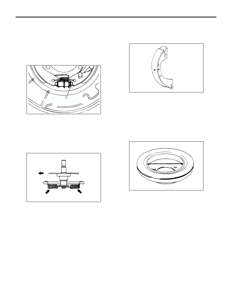
>>A<< ADJUSTER ASSEMBLY INSTALLATION

Install the adjuster so that the shoe adjusting bolt for 
the left hand wheel is attached towards the rear of 
the vehicle, and the shoe adjusting bolt for the right 
hand wheel is towards the front of the vehicle.

>>B<< SHOE-TO-ANCHOR SPRING 
INSTALLATION

The shoe-to-anchor springs are not interchangeable 
as their constants are different. The one with blue 
paint mark should be install at the front of the vehicle, 
and the other with yellow paint at the rear of the 
vehicle, respectively.
NOTE: The illustration shows the left rear wheel. The 
right rear wheel is symmetrical to that.

INSPECTION

M1361002600301

PARKING BRAKE LINING AND BRAKE 
DRUM CHECK

1. Measure the thickness of the brake lining at 

several places.

Standard value: 2.8 mm
Limit: 1.0 mm

2. If the thickness of the brake lining is below the 

limit, replace the shoe and lining assemblies on 
both sides of the vehicle. Never replace only one 
side.

3. Measure the inside diameter of the brake disc in 

two places or more.

Standard value: 168.0 mm
Limit: 169.0 mm

4. If the inside diameter exceeds the limit, or if it is 

excessively worn on one side, replace the brake 
disc.

AC202301AC

Shoe adjusting bolt

AC202302AC

Front of the vehicle

Blue paint

Yellow paint

ACX00708AB

ACX00709

NOTES

37-1

GROUP 37

POWER STEERING

CONTENTS

GENERAL INFORMATION . . . . . . . .

37


SERVICE SPECIFICATIONS. . . . . . .

37


LUBRICANTS  . . . . . . . . . . . . . . . . . .

37


SEALANTS  . . . . . . . . . . . . . . . . . . . .

37


SPECIAL TOOLS. . . . . . . . . . . . . . . .

37


ON-VEHICLE SERVICE. . . . . . . . . . .

37


STEERING WHEEL FREE PLAY CHECK . 

37


STEERING ANGLE CHECK . . . . . . . . . . . . 

37


TIE ROD END BALL JOINT 
STARTING TORQUE CHECK 
 . . . . . . . . . . 

37


STATIONARY STEERING EFFORT CHECK

37


STEERING WHEEL RETURN TO 
CENTRE CHECK . . . . . . . . . . . . . . . . . . . . 

37


DRIVE BELT TENSION CHECK. . . . . . . . . 

37


FLUID LEVEL CHECK  . . . . . . . . . . . . . . . . 

37


FLUID REPLACEMENT . . . . . . . . . . . . . . . 

37


POWER STEERING SYSTEM AIR 
BLEEDING  . . . . . . . . . . . . . . . . . . . . . . . . . 

37


OIL PUMP PRESSURE TEST  . . . . . . . . . . 

37


POWER STEERING PRESSURE 
SWITCH CHECK  . . . . . . . . . . . . . . . . . . . . 

37


TIE ROD END BALL JOINT DUST 
COVER CHECK . . . . . . . . . . . . . . . . . . . . . 

37


STEERING COLUMN SHAFT ASSEMBLY 
SHOCK ABSORBING MECHANISM CHECK

37


STEERING WHEEL*. . . . . . . . . . . . . .

37


REMOVAL AND INSTALLATION  . . . . . . . . 

37


STEERING SHAFT* . . . . . . . . . . . . . .

37


REMOVAL AND INSTALLATION  . . . . . . . . 

37


DISASSEMBLY AND REASSEMBLY . . . . . 

37


POWER STEERING GEAR BOX AND 
LINKAGE* . . . . . . . . . . . . . . . . . . . . . .

37


REMOVAL AND INSTALLATION  . . . . . . . . 

37


INSPECTION. . . . . . . . . . . . . . . . . . . . . . . . 

37


DISASSEMBLY AND REASSEMBLY . . . . . 

37


TIE ROD END BALL JOINT 
DUST COVER REPLACEMENT . . . . . . . . . 

37


POWER STEERING OIL PUMP 
ASSEMBLY. . . . . . . . . . . . . . . . . . . . .

37


REMOVAL AND INSTALLATION  . . . . . . . . 

37


INSPECTION. . . . . . . . . . . . . . . . . . . . . . . . 

37


DISASSEMBLY AND REASSEMBLY . . . . . 

37


INSPECTION. . . . . . . . . . . . . . . . . . . . . . . . 

37


POWER STEERING HOSES  . . . . . . .

37


REMOVAL AND INSTALLATION  . . . . . . . . 

37


:$51,1*65(*$5',1*6(59,&,1*2)6833/(0(17$/5(675$,176<67(0 656 (48,33('9(+,&/(6

œ

Improper service or maintenance of any component of the SRS, or any SRS-related component, can lead to 
personal injury or death to service personnel (from inadvertent firing of the air bag) or to the driver and 
passenger (from rendering the SRS inoperative).

œ

Service or maintenance of any SRS component or SRS-related component must be performed only at an 
authorized MITSUBISHI dealer.

œ

MITSUBISHI dealer personnel must thoroughly review this manual, and especially its GROUP 52B - Supplemental 
Restraint System (SRS) before beginning any service or maintenance of any component of the SRS or any SRS-
related component.

WARNING

00

11

12

13

14

15

16

17

21

22

25

26

27

31

32

33

34

35

36

37

51

52

42

54

55

GENERAL INFORMATION

POWER STEERING

37-2

GENERAL INFORMATION

M1372000100326

FEATURES

Power steering has been adopted in all vehicles to 
make the steering system easier to handle.

œ

A 4-spoke steering wheel is used.

œ

A steering column has a shock absorbing 
mechanism and a tilt steering mechanism.

œ

Integral-type rack and pinion gear with high 
rigidity and excellent response is used. 

œ

A vane type pump with a fluid flow rate control 
system which change steering effort according to 
the engine speed is used. 

œ

The separate plastic resin oil reservoir is used to 
reduce weight and to make the fluid level 
checking easier. 

œ

The cooler tube assembly is installed on the 
power steering fluid line to improve the cooling 
performance of the power steering fluid.

SPECIFICATIONS

Item

Specification

Steering wheel

Type

4-spoke type

Outside diameter mm

380

Maximum number of turns

2.7

Steering column

Column mechanism

Shock absorbing mechanism and Tilt 
steering mechanism
Tilt up: 20 mm
Tilt down: 20 mm

Power steering type

Integral type

Oil pump

Type

Vane pump

Basic discharge amount mL/rev.

9.6

Relief pressure MPa

8.8

Reservoir type

Separate type (plastic)

Pressure switch

Equipped

Steering gear

Type

Rack and pinion

Stroke ratio (Rack stroke/Steering wheel 
maximum turning radius)

51.45

Rack stroke mm

141


Content   ..  283  284  285  286   ..