Mitsubishi Outlander (2003+). Manual - part 275
 

  Index      Mitsubishi     Mitsubishi Outlander - service repair manual 2003 year


Search            


Content   ..  273  274  275  276   ..


Mitsubishi Outlander (2003+). Manual - part 275


TROUBLESHOOTING

ANTI-SKID BRAKING SYSTEM (ABS)

35B-43

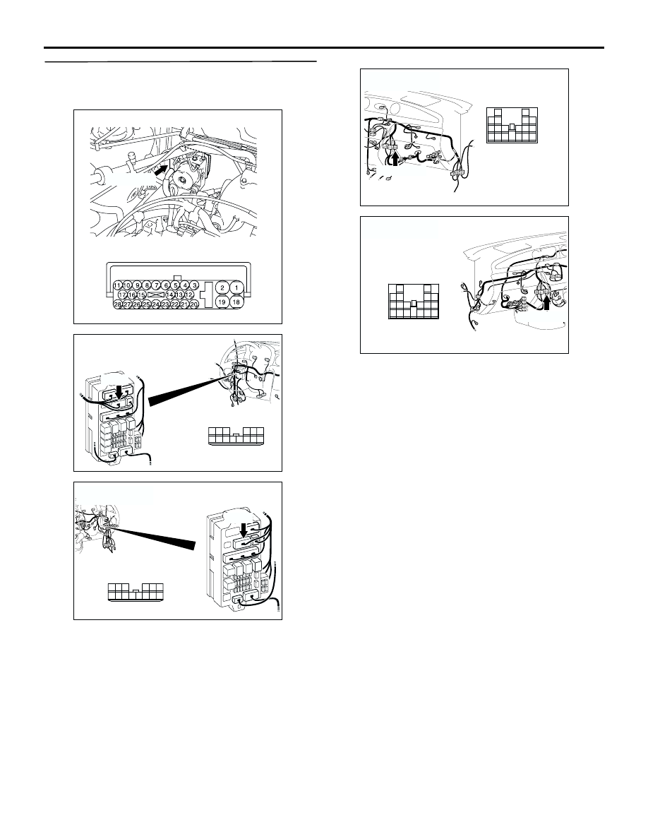
STEP 2. Check the harness wire between 
junction block connector C-202 terminal 8 and 
ABS-ECU connector B-03 terminal 20.

NOTE: 

After inspecting ABS-ECU connector B-03, junction 
block connector C-202 and intermediate connector 
C-106, inspect the wire. If any of these connectors is 
damaged, repair or replace it. Then go to Step 5.

Q: Is the harness wire between junction block 

connector C-202 terminal 8 and ABS-ECU 
connector B-03 terminal 20 damaged?

YES : 

Repair it and go to Step 5.

NO : 

This malfunction is intermittent. Refer to 
GROUP 00, How to Use 
Troubleshooting/Inspection Service Points 


How to Cope With Intermittent Malfunction 

P.00-6

.

AC301441AB

Connector: B-03

B-03 (GR)

Harness side

AC308720

C-202

Harness side

10

1

6

14

5

12

13

4

11

7

2

3

8

9

AM

Connector: C-202
<LHD>

AC308772

C-202

Harness side

10

1

6

14

5

12

13

4

11

7

2

3

8

9

Connector: C-202
<RHD>

AL

AC308718

C-106 (GR)

13

3

7

16

19

15

14

18

17

12

6

4

8

1

9

11

10

5

2

Connector: C-106
<LHD>

AS

AC308735

AX

C-106 (GR)

Connector: C-106
<RHD>

13

3

7

16

19

15

14

18

17

12

6

4

8

1

9

11

10

5

2

TROUBLESHOOTING

ANTI-SKID BRAKING SYSTEM (ABS)

35B-44

STEP 3. Check the harness wires between 
ABS-ECU connector B-03 (terminals 4 and 13) 
and diagnosis connector C-24 (terminals 1 and 
7).

AC301441AB

Connector: B-03

B-03 (GR)

Harness side

AC308717

Connectors: C-02, C-24 <LHD>

C-24(B)

C-24 Harness side

AT

C-02

C-02

AC308770

AH

Connectors: C-02, C-24 <RHD>

C-02

33

22

11

28

17

16

15

14

13

12

25

2324

2627

3

1 2

4 5

21

20

19

18

2930

32

31

7

6

8

10

9

C-02

C-24(B)

C-24 Harness side

TROUBLESHOOTING

ANTI-SKID BRAKING SYSTEM (ABS)

35B-45

NOTE: 

After inspecting ABS-ECU connector B-03, diagnosis 
connector C-24, and intermediate connectors C-02, 
C-104 and C-105, inspect the wires. If any of these 
connectors is damaged, repair or replace it. Then go 
to Step 5.

Q: Is any of the harness wires between ABS-ECU 

connector B-03 (terminals 4 and 13) and diagnosis 
connector C-24 (terminals 1 and 7) damaged?

YES : 

Repair it and go to Step 5.

NO : 

Go to Step 4.

STEP 4. Check the harness wires between 
ABS-ECU connector B-03 (terminals 2 and 18) 
and earth (No.9).

Q: Is any of the harness wires between ABS-ECU 

connector B-03 (terminals 2 and 18) and earth 
(No.9) damaged?

YES : 

Repair it and then go to Step 5.

NO : 

Check the troubleshooting condition. To 
reproduce the troubleshooting state replace 
the hydraulic unit (integrated with 
ABS-ECU).Then go to Step 5. If the state of 
failure is not reproduced then a intermittent 
malfunction is suspected. Refer to GROUP 
00, How to Use Troubleshooting/Inspection 
Service Points 

 How to Cope with 

Intermittent Malfunction 

P.00-6

.

AC308719

C-105

AK

Connectors: C-104, C-105
<LHD>

C-104(B)

C-105

C-104(B)

10

1

21

16

13

4

11

2

12

3

1415

1718

5

20

7

19

6

8

22

9

15

1
8

3

10

2
9

11

4

13

12

5

14

16

7

6

AC308736

C-105

AI

C-104(B)

Connectors: C-104, C-105
<RHD>

C-105

C-104(B)

15

1
8

3

10

2
9

11

4

13

12

5

14

16

7

6

10

1

21

16

13

4

11

2

12

3

1415

1718

5

20

7

19

6

8

22

9

AC301441AB

Connector: B-03

B-03 (GR)

Harness side

AC208089AC

Relay box

Earth (No.9)

TROUBLESHOOTING

ANTI-SKID BRAKING SYSTEM (ABS)

35B-46

STEP 5. Retest the system.

Q: Does the MUT-II/III communicate with the ABS 

system?

YES : 

The procedure is complete.

NO : 

Start over at Step 1.

INSPECTION PROCEDURE 2: When the Ignition Key is Turned to the "ON" position (Engine Stopped), 
the ABS Warning Lamp does not Illuminate.

OPERATION

The ABS warning lamp is lit up by transistor 
control in the ABS-ECU. However, the 
relationship of the reverse circuit movement in 
the combination meter will vary from usual in 
terms of transistor ON/OFF and ABS warning 
lamp ON/OFF, in that the ABS warning lamp will 

lamp up when the transistor is turned OFF for this 
circuit. This is how the ABS warning lamp lights 
up even when the ABS-ECU connector is 
connected improperly or if the ABS-ECU function 
has terminated.

The ABS-ECU also lights up the ABS warning 
lamp during the initial check (approximately 3 
seconds) when the ignition switch is turned to the 
"ON" position in addition to when the system is 
malfunctioning.

ABS-ECU

IGNITION
SWITCH (IG1)

COMBINATION
METER

<LHD>

CPU

<RHD>

<LHD>

<RHD>

Wire colour code
B : Black     LG : Light green     G : Green     L : Blue     W : White     Y : Yellow     SB : Sky blue
BR : Brown     O : Orange     GR : Gray     R : Red     P : Pink     V : Violet   

ABS Warning Lamp Circuit


Content   ..  273  274  275  276   ..