Mitsubishi Outlander (2003+). Manual - part 274


  Index      Mitsubishi     Mitsubishi Outlander - service repair manual 2003 year


Search            


Content   ..  272  273  274  275   ..


Mitsubishi Outlander (2003+). Manual - part 274


TROUBLESHOOTING

ANTI-SKID BRAKING SYSTEM (ABS)

35B-39

NOTE: 

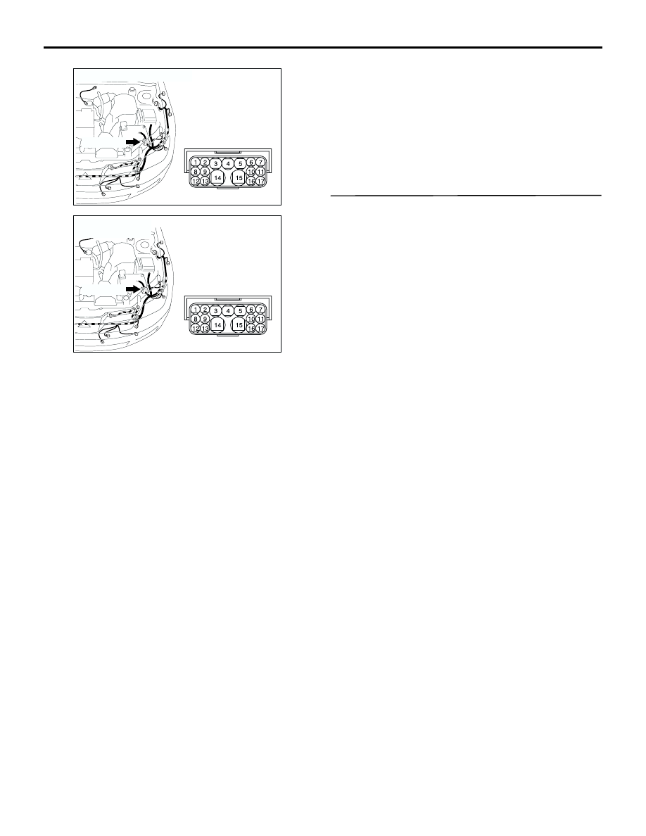
 After inspecting intermediate connector A-14, 
inspect the wire. If the connector is damaged, repair 
or replace it. Then go to Step 3.

Q: Is any harness wire between fusible link number 3 

and ABS-ECU connector B-03 (terminal 1 and 19) 
damaged?

YES : 

Repair it and go to Step 3.

NO : 

This malfunction is intermittent. Refer to 
GROUP 00, How to Use 
Troubleshooting/Inspection Service Points 


How to Cope With Intermittent Malfunction 

P.00-6

.

STEP 3. Check whether the diagnosis code is 
reset.

Q: Is diagnosis code No.41, 42, 43, 44, 52, 53 or 55 

set?

YES : 

Start over at Step 1.

NO : 

The procedure is complete.

AC308679 AG

A-14(GR)

Connector: A-14 <LHD>

AC308686AH

A-14(GR)

Connector: A-14
<RHD>

TROUBLESHOOTING

ANTI-SKID BRAKING SYSTEM (ABS)

35B-40

INSPECTION CHART FOR TROUBLE 
SYMPTOMS

M1352011400664

NOTE: If steering movements are made when 
driving at high speed, or when driving on road 
surfaces with low frictional resistance, or when 
passing over bumps, the ABS may operate although 
sudden braking is not being applied. Because of this, 
when getting information from the customer, check if 
the problem occurred while driving under such 
conditions as these.

NOTE: During ABS operation, the brake pedal may 
vibrate a little or may not be able to be pressed. Such 
conditions are due to intermittent changes in 
hydraulic pressure inside the brake line to prevent 
the wheels from locking. This is normal.

Trouble symptoms

Inspection procedure No. Reference page

Communication between MUT-II/III and the whole 
system is not possible.

GROUP 13A, 
Diagnosis 

P.13A-190

Communication between MUT-II/III and the 
ABS-ECU is not possible.

1

P.35B-41

When the ignition switch is turned to the "ON" 
position (Engine stopped), the ABS warning lamp 
does not illuminate.

2

P.35B-46

The ABS warning lamp remains illuminated after the 
engine is started.

3

P.35B-52

Faulty ABS operation

4

P.35B-55

TROUBLESHOOTING

ANTI-SKID BRAKING SYSTEM (ABS)

35B-41

INSPECTION PROCEDURE FOR 
TROUBLE SYMPTOMS

INSPECTION PROCEDURE 1: Communication between MUT-II/III and the ABS-ECU is not Possible.

NOTE

: LHD
: RHD

IGNITION 
SWITCH (IG2)

ABS-ECU

POWER 
SOURCE

DIAGNOSIS 
CONNECTOR

FRONT SIDE

Wire colour code
B : Black     LG : Light green     G : Green     L : Blue     W : White     Y : Yellow     SB : Sky blue
BR : Brown     O : Orange     GR : Gray     R : Red     P : Pink     V : Violet   

Diagnosis Connector Circuit

TROUBLESHOOTING

ANTI-SKID BRAKING SYSTEM (ABS)

35B-42

OPERATION

The diagnostic output is made from the 
ABS-ECU (terminal 13) to the diagnosis output 
terminal (terminal 7) of the diagnosis connector.

When the diagnosis connector's diagnosis test 
mode control terminal (terminal 1) is grounded, 
the ABS-ECU (terminal 4) will go into diagnosis 
mode.

COMMENT ON TROUBLE SYMPTOM
When communication with the MUT-II/III is not 
possible, the cause is probably an open circuit in the 
ABS-ECU power circuit or an open circuit in the 
diagnostic output circuit.

PROBABLE CAUSES
The most likely causes for this case are:

Blown fuse

Damaged wiring harness or connector

Malfunction of the hydraulic unit (Integrated with 
ABS-ECU)

DIAGNOSIS

STEP 1. Voltage measurement at the ABS-ECU 
connector B-03.

(1) Disconnect ABS-ECU connector B-03 and 

measure at the harness side.

(2) Start the engine.

(3) Measure the voltage between terminal 20 and 

earth.

OK: System voltage

Q: Is the check result normal? 

YES : 

Go to Step 3.

NO : 

Go to Step 2.

AC301441AB

Connector: B-03

B-03 (GR)

Harness side

AC301683AE

Connector B-03 
(harness side)


Content   ..  272  273  274  275   ..