Mitsubishi Outlander (2003+). Manual - part 272
TROUBLESHOOTING
ANTI-SKID BRAKING SYSTEM (ABS)
35B-31
STEP 5. Check the harness wire between
G-sensor connector D-35 terminal 3 and
ABS-ECU connector B-03 terminal 8.
NOTE:
<R.H. drive vehicles> After inspecting the G-sensor
connector D-35, intermediate connectors C-13,
C-106, and ABS-ECU connector B-03, inspect the
wire. If any of these connector is damaged, repair or
replace it. Then go to Step 8.
Q: Is the harness wire between G-sensor connector
D-35 terminal 3 and ABS-ECU connector B-03
terminal 8 damaged?
YES :
Repair it and go to Step 8.
NO :
Erase the diagnosis code memory, and
recheck if any diagnosis code sets. If
diagnosis code No.32 sets, replace the
hydraulic unit (integrated with ABS-ECU)
and then go to Step 8 .
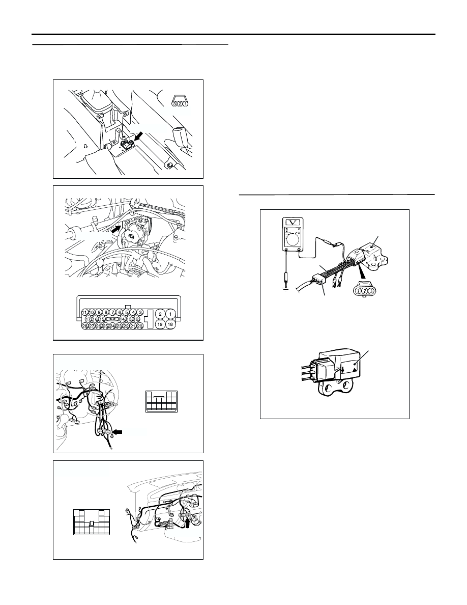
STEP 6. Check G-sensor output voltage.
(1) Disconnect G-sensor connector D-35, and
connect special tool harness set (MB991348)
between the disconnected connectors.
(2) Turn the ignition switch to the "ON" position.
(3) Measure the voltage between terminal 2 and
earth.
OK:
When vehicle is stationary (level): 2.4
−
2.6 V
When vehicle is being driven: 1.0
−
4.0 V
Q: Is G-sensor output voltage normal?
YES :
Go to Step 7.
NO :
Replace the G-sensor and go to Step 8.
AC301440AB
Connector: D-35
D-35 (B)
Harness side
AC301441AB
Connector: B-03
B-03 (GR)
Harness side
AC308769
AX
C-13(L)
Connector: C-13
<RHD>
10
1
4
2 3
13
7
12
11
5 6
15
14
8 9
AC308735
AX
C-106 (GR)
Connector: C-106
<RHD>
13
3
7
16
19
15
14
18
17
12
6
4
8
1
9
11
10
5
2
AC103662AK
MB991348
Connector: D-35
(Harness side)
Label
Label