Mitsubishi Outlander (2003+). Manual - part 270
TROUBLESHOOTING
ANTI-SKID BRAKING SYSTEM (ABS)
35B-23
NOTE:
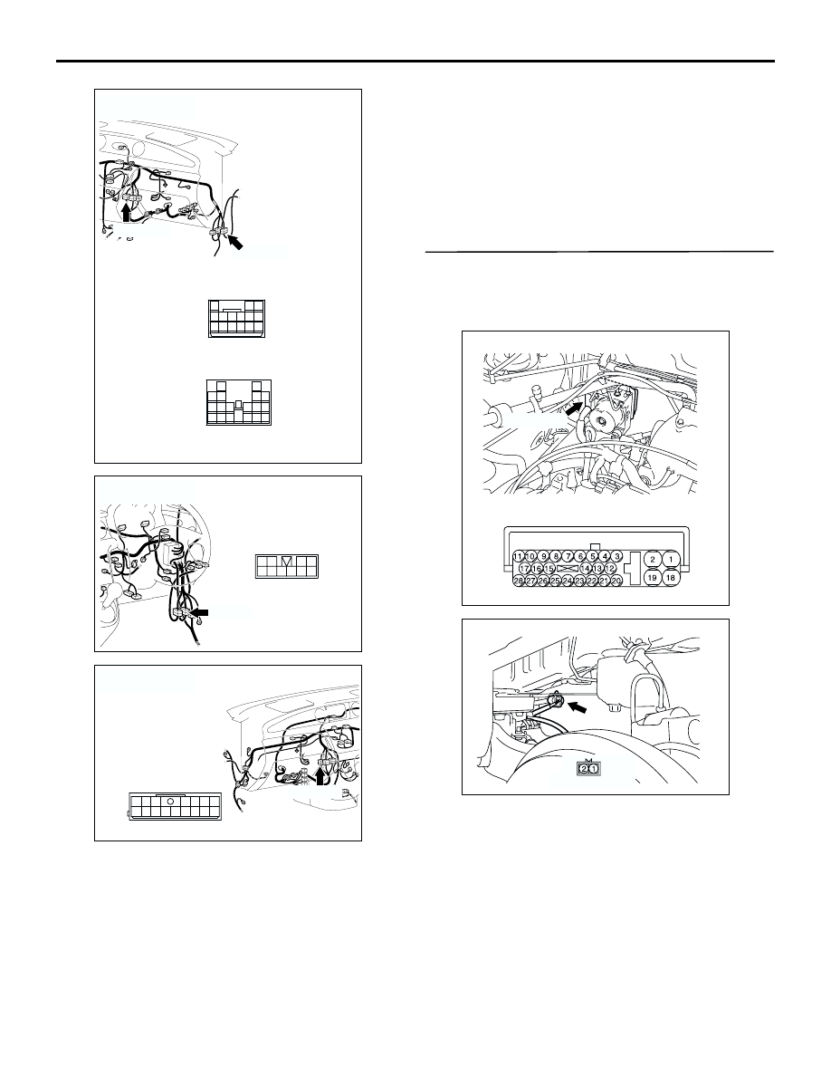
After inspecting ABS-ECU connector B-03,
intermediate connectors C-14 and C-104, and ABS
sensor <front: RH> connector A-31, inspect the wire.
If any of these connectors is damaged, repair or
replace it. Then go to Step 11.
Q: Is any harness wire between ABS-ECU connector
B-03 (terminals 10 and 9) and ABS sensor <front:
RH> connector A-31 (terminals 1 and 2) damaged?
YES :
Repair it and go to Step 11.
NO :
This malfunction is intermittent. Refer to
GROUP 00, How to Use
Troubleshooting/Inspection Service Points
−
How to Cope With Intermittent Malfunction
.
STEP 7. Check the harness wires between
ABS-ECU connector B-03 (terminals 28 and 27)
and ABS sensor <rear: LH> connector D-22
(terminals 1 and 2).
AC308719
C-14
AI
C-104(B)
Connectors: C-14, C-104
<LHD>
C-104(B)
C-14
13
3
7
16
19
15
14
18
17
12
6
4
8
1
9
11
10
5
2
10
1
4
2 3
13
7
12
11
5 6
15
14
8 9
AC308769
AY
C-14
Connector: C-14
<RHD>
9
3
2
1
5 6 7 8
4
10
AC308735
AV
C-104 (B)
Connector: C-104
<RHD>
15
1
8
3
10
2
9
11
4
13
12
5
14
16
7
6
AC301441AB
Connector: B-03
B-03 (GR)
Harness side
AC301446AB
Connector: D-22
D-22 (B)
Harness side