Mitsubishi Outlander (2003+). Manual - part 266


  Index      Mitsubishi     Mitsubishi Outlander - service repair manual 2003 year


Search            


Content   ..  264  265  266  267   ..


Mitsubishi Outlander (2003+). Manual - part 266


TROUBLESHOOTING

ANTI-SKID BRAKING SYSTEM (ABS)

35B-7

5. Turn the ignition switch to the "LOCK" (OFF) 

position.

6. Disconnect special tool diagnosis code check 

harness (MB991529).

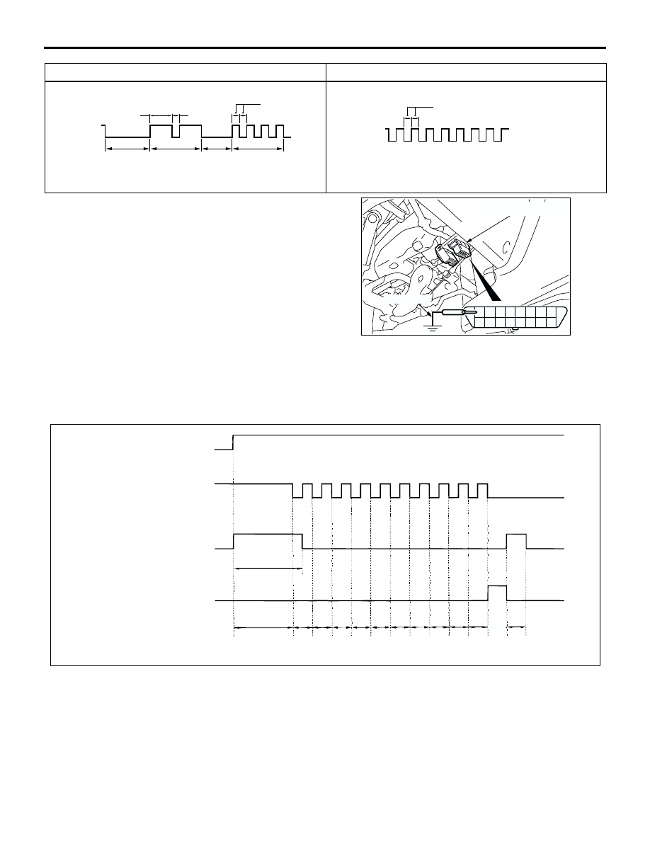
ERASING DIAGNOSIS CODES

When Using the MUT-II/III
Refer to GROUP 00, How to Use 
Troubleshooting/Inspection Service Points 

P.00-6

.

When not Using the MUT-II/III
NOTE:  If the ABS-ECU functions have stopped due 
to the fail-safe function, the diagnosis code cannot 
be erased.
1. Turn the ignition switch to the "LOCK" (OFF) 

position.

2. Use special tool diagnosis code check harness 

(MB991529) to earth terminal number 1 of the 
diagnosis connector.

3. Depress the brake pedal and hold it.
4. Turn the ignition switch to the "ON" position.
5. After turning the ignition switch to the "ON", 

release the pedal within three seconds. Repeat 
this process of pressing and releasing the brake 
pedal 10 continuous times.

6. Turn the ignition switch to the "LOCK" (OFF) 

position.

7. Disconnect special tool diagnosis code check 

harness (MB991529).

When the diagnosis code No.24 is set

When no diagnosis code is set

ACX01777

Illuminated

Switched
off

Pause
time
3 secs.

Tens
signal

Place
division
2 secs.

Units
signal

1.5 secs.

0.5 sec.

0.5 sec.

AD

ACX01778

Illuminated

Switched
off

0.25 sec.

AD

AC107528 AH

1 2 3 4 5 6 7 8

9 10 11 12 13 14 15 16

MB991529

Diagnosis connector

AC000937

Ignition switch

ON

OFF(OFF)

Stop lamp switch

ON

OFF

ABS warning lamp

ON

OFF

ABS-ECU memory

3 sconds

Within
3 sconds

Within
1
seconds

Erasing of ABS-ECU
diagnosis codes complete.

AD

1st

2nd

3rd

4th

5th

6th

7th

8th

9th

10th

Within
1
seconds

Within
1
seconds

Within
1
seconds

Within
1
seconds

Within
1
seconds

Within
1
seconds

Within
1
seconds

Within
1
seconds

Within
1
seconds

1
seconds

TROUBLESHOOTING

ANTI-SKID BRAKING SYSTEM (ABS)

35B-8

INSPECTION CHART FOR DIAGNOSIS 
CODE

M1352011300708

Follow the inspection chart that is appropriate for the 
diagnosis code.

NOTE: diagnosis code No.16, 52, 63

.

Code No.16 is cleared from the memory by turning the ignition switch to the "ACC" position. When the 
system is properly reset, this code is also cleared from the memory.

Code No.52 and 63 are cleared from the memory by turning the ignition switch to the "ACC" position.

Diagnosis code 
No.

Inspection item

Diagnostic content

Reference page

11

Front right ABS sensor

Open circuit or short circuit

P.35B-9

12

Front left ABS sensor

13

Rear right ABS sensor

14

Rear left ABS sensor

16

ABS-ECU power supply system ABS-ECU power supply 

voltage below or above the 
specified value. Not 
displayed if the voltage 
recovers.

P.35B-17

21

Front right ABS sensor

P.35B-19

22

Front left ABS sensor

23

Rear right ABS sensor

24

Rear left ABS sensor

32

G sensor system <4WD>

P.35B-27

33

Stop lamp switch system

P.35B-33

41

ABS front right solenoid valve

P.35B-37

42

ABS front left solenoid valve

43

ABS rear right solenoid valve

44

ABS rear left solenoid valve

51

Valve relay problem (stays on)

Replace the hydraulic 
unit (Integrated with 
ABS-ECU).

52

Valve relay problem (stays off)

P.35B-37

53

Motor relay problem (stays off)

54

Motor relay problem (stays on)

Replace the hydraulic 
unit (Integrated with 
ABS-ECU).

55

Motor system (seized pump motor)

P.35B-37

63

ABS-ECU abnormality

Improperly installed ABS-ECU <2WD>

Replace the hydraulic 
unit (Integrated with 
ABS-ECU).

TROUBLESHOOTING

ANTI-SKID BRAKING SYSTEM (ABS)

35B-9

DIAGNOSTIC TROUBLE CODE 
PROCEDURES

Code No.11, 12, 13 and 14: ABS Sensor (Open Circuit or Short Circuit)

OPERATION

A toothed ABS rotor generates a voltage pulse as 
it moves across the pickup field of each ABS 
sensor.

The amount of voltage generated at each wheel 
is determined by the clearance between the ABS 
rotor teeth and the ABS sensor, and by the speed 
of rotation.

The ABS sensors transmit the frequency of the 
voltage pulses and the amount of voltage 
generated by each pulse to the ABS-ECU.

The hydraulic unit modulates the amount of 
braking force individually applied to each wheel 
cylinder.

ABS SENSOR

(FRONT: LH)

(FRONT: RH)

(REAR: LH)

(REAR: RH)

ABS-ECU

Wire colour code
B : Black     LG : Light green     G : Green     L : Blue     W : White     Y : Yellow     SB : Sky blue
BR : Brown     O : Orange     GR : Gray     R : Red     P : Pink     V : Violet   

AC301686AB

ABS Sensor Circuit

TROUBLESHOOTING

ANTI-SKID BRAKING SYSTEM (ABS)

35B-10

DIAGNOSIS CODE SET CONDITIONS
Diagnosis codes No.11, 12, 13 and 14 are set when 
signal is not input due to breakage of the wires of the 
four ABS sensors.

PROBABLE CAUSES
The most likely causes for these diagnosis codes to 
set are:

Malfunction of the ABS sensor

Damaged wiring harness or connector

Malfunction of the hydraulic unit (integrated with 
ABS-ECU)

DIAGNOSIS

STEP 1. MUT-II/III data list

Set MUT-II/III to data reading mode, and check the 
data list items by driving the vehicle.

Item 01: Front right ABS sensor

Item 02: Front left ABS sensor

Item 03: Rear right ABS sensor

Item 04: Rear left ABS sensor

OK: The reading on the speedometer nearly 
matches the indication on MUT-II/III, when 
driving.

Q: Is the ABS sensor input normal?

YES : 

This malfunction is intermittent. Refer to 

GROUP 00, How to Use 
Troubleshooting/Inspection Service Points 


How to Cope With Intermittent Malfunction 

P.00-6

NO : 

Go to Step 2.

STEP 2. Inspect the ABS sensor.

Refer to 

P.35B-68

.

Check items:

ABS sensor internal resistance: 1.24 

 1.64 k

Insulation between the ABS sensor body and the 
connector terminals

Q: Is the ABS sensor damaged?

YES : 

 Replace it and then go to Step 8.

NO : 

Go to Step 3.

STEP 3. Resistance measurement at ABS-ECU 
connector B-03.

(1) Disconnect ABS-ECU connector B-03 and 

measure at the harness side.

(2) Measure the resistance between ABS-ECU 

connector terminals 16 and 26, 9 and 10, 27 and 
28, or 11 and 17.

Standard Value: 1.24 

 1.64 k

Q: Is the resistance between terminals 16 and 26, 9 

and 10, 27 and 28, or 11 and 17 within the standard 
value?

When resistances between all terminals are within 
the standard value : 

Erase the diagnosis code 

memory, and recheck if any diagnosis code 
sets. If diagnosis code No.11, 12, 13 or 14 
sets, replace the hydraulic unit (integrated 
with ABS-ECU). Then go to Step 8.

When resistance between terminals 16 and 26 is 
not within the standard value : 

Go to Step 4.

When resistance between terminals 9 and 10 is not 
within the standard value : 

Go to Step 5.

When resistance between terminals 27 and 28 is 
not within the standard value : 

Go to Step 6.

When resistance between terminals 11 and 17 is 
not within the standard value : 

Go to Step 7.

AC301441AB

Connector: B-03

B-03 (GR)

Harness side

AC301683

Connector B-03
(harness side)

AB


Content   ..  264  265  266  267   ..