Mitsubishi Outlander (2003+). Manual - part 264
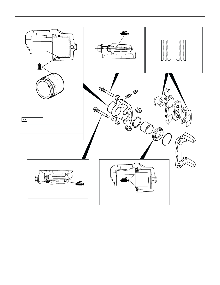
REAR DISC BRAKE ASSEMBLY
BASIC BRAKE SYSTEM
35A-27
LUBRICATION POINTS
AC202232
AC203550
Piston seal
Brake fluid: DOT 3 or DOT 4
AC
Grease: Repair kit grease
The piston seal inside the seal and boot
kit is coated with a special grease.
Do not wipe this grease off.
! CAUTION
Grease: Repair kit grease
Grease: Repair kit grease
Grease: Repair kit grease