Mitsubishi Outlander (2003+). Manual - part 263


  Index      Mitsubishi     Mitsubishi Outlander - service repair manual 2003 year


Search            


Content   ..  261  262  263  264   ..


Mitsubishi Outlander (2003+). Manual - part 263


FRONT DISC BRAKE ASSEMBLY

BASIC BRAKE SYSTEM

35A-23

DISASSEMBLY SERVICE POINTS

When disassembling the disc brakes, disassemble 
both sides (left and right) as a set.
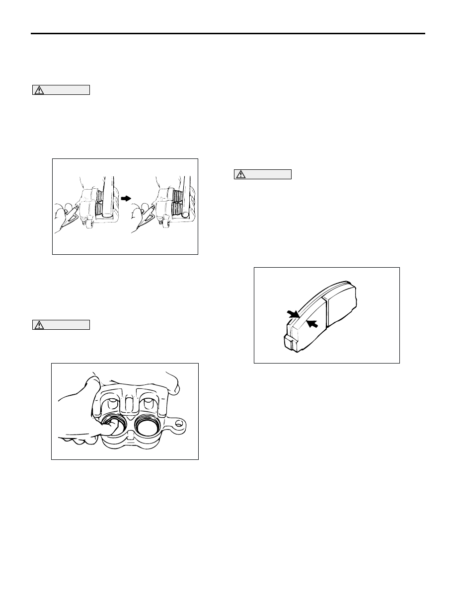
<<A>> PISTON BOOT/PISTON REMOVAL

CAUTION

Blow air little by little to remove the pistons. 
The pistons will rush out if a force of air is 
applied suddenly.

If one piston has been removed completely, it 
will become impossible to remove the second 
piston.

Remove the pistons and the piston boots by pumping 
in air from the brake hose connection. Be sure to use 
the handle of a plastic hammer and adjust the height 
of the two pistons so that the pistons protrude evenly.

<<B>> PISTON SEAL REMOVAL

CAUTION

Do not use a flat-tipped screwdriver or similar 
tool to remove the piston seal. These may 
damage the inner side of the cylinder.

1. Remove the piston seal with your finger tip.
2. Clean the piston surface and inner cylinder with 

alcohol or brake fluid DOT 3 or DOT 4.

INSPECTION

M1351006300345

Check the cylinder for wear, damage or rust.

Check the piston surface for wear, damage or 
rust.

Check the caliper body or sleeve for wear.

Check the pad for damage or adhesion of grease, 
check the backing metal for damage.

PAD WEAR CHECK

WARNING

Always replace both brake pads on each 
wheel as a set. Failure to do so will result 
in uneven braking, which may cause 
unreliable brake operation.

If there is significant difference in the 
thickness of the pads on the left and right 
sides, check the sliding condition of the 
piston and slide pins.

1. Measure thickness at the thinnest and most worn 

area of the pad.

Standard value: 10.0 mm
Minimum limit: 2.0 mm

2. Replace the pad assembly if pad thickness is less 

than the limit value.

AC202257

AC301355AB

ACX00690

REAR DISC BRAKE ASSEMBLY

BASIC BRAKE SYSTEM

35A-24

REAR DISC BRAKE ASSEMBLY

REMOVAL AND INSTALLATION

M1351007000358

INSTALLATION SERVICE POINTS

>>A<< REAR BRAKE ASSEMBLY INSTALLATION

1. In order to measure the brake drag torque, 

measure the hub torque with the pads removed by 
the following procedure.

Use a spring balance to measure the hub torque 
in the forward direction. Record hub torque with 
pads removed.

CAUTION

Do not let any oil, grease or other contamination 
get onto the friction surfaces of the pads and 
brake discs.
2. After re-installing the caliper support to the 

backing plate, install the pad clips and the pads to 
the caliper support.

3. Clean the piston and insert into cylinder with 

special tool disc brake piston expander 
(MB990520).

4. Be careful that the piston boot does not become 

caught, when lowering the caliper assembly and 
installing the lock pin.

AC201830AC

60 ± 5 N·m

15 ± 2 N·m

1

2

3

Removal steps

Brake fluid draining

1. Brake hose connection
2. Rear brake assembly
3. Rear brake disc

Installation steps

3. Rear brake disc

>>A<<

2. Rear brake assembly
1. Brake hose connection

Brake fluid supplying and air bleeding 
(Refer to 

P.35A-7

).

>>B<<

Brake drag force check

AC201814

AC301357

MB990520

AB

REAR DISC BRAKE ASSEMBLY

BASIC BRAKE SYSTEM

35A-25

>>B<< BRAKE DRAG FORCE CHECK
1. Check the brake drag force as follows.

(1) Start the engine and hold the brake pedal 

down for 5 seconds. (Pedal depression force: 
approximately 200 N)

(2) Stop the engine.
(3) Turn the brake disc forward 10 times.

(4) Use a spring balance to measure the hub 

torque with pads installed in the same 
direction as earlier.

(5) Calculate the drag force of the disc brake 

[difference between hub torque with pads 
installed and hub torque with pads removed].

Standard value: 68 N or less

2. If the brake drag force exceeds the standard 

value, disassemble and clean the piston. Check 
for corrosion or worn piston seal, and check the 
sliding condition of the lock pin and guide pin.

INSPECTION

M1351007100236

BRAKE DISC CHECK
Disc wear (Refer to 

P.35A-10

).

Disc run-out (Refer to 

P.35A-10

).

AC201815

REAR DISC BRAKE ASSEMBLY

BASIC BRAKE SYSTEM

35A-26

DISASSEMBLY AND REASSEMBLY

M1351007200233

AC203578

1

3

2

5

5

9

7

8

6

4

10

11

11

14

8

9

2

5

5

6

1

2

4

5

3

6

8

7

9

5

10

44 ± 5 N·m

7.9 ± 0.9 N·m

44 ± 5 N·m

AE

13

13

13

13

11

14

12

15

12

12

15

15

Brake caliper kit

Pad set

Shim set

Seal and boot repair kit

Clip set

Grease

Grease

Disassembly steps

1. Lock pin
2. Bushing
3. Guide pin
4. Caliper support
5. Pin boot
6. Boot ring

<<A>>

7. Piston

<<A>>

8. Piston boot

<<B>>

9. Piston seal
10. Caliper body
11. Pad and wear indicator assembly
12. Inner shim
13. Clip
14. Pad assembly
15. Outer shim

Disassembly steps (Continued)


Content   ..  261  262  263  264   ..