Mitsubishi Outlander (2003+). Manual - part 258
SERVICE SPECIFICATIONS
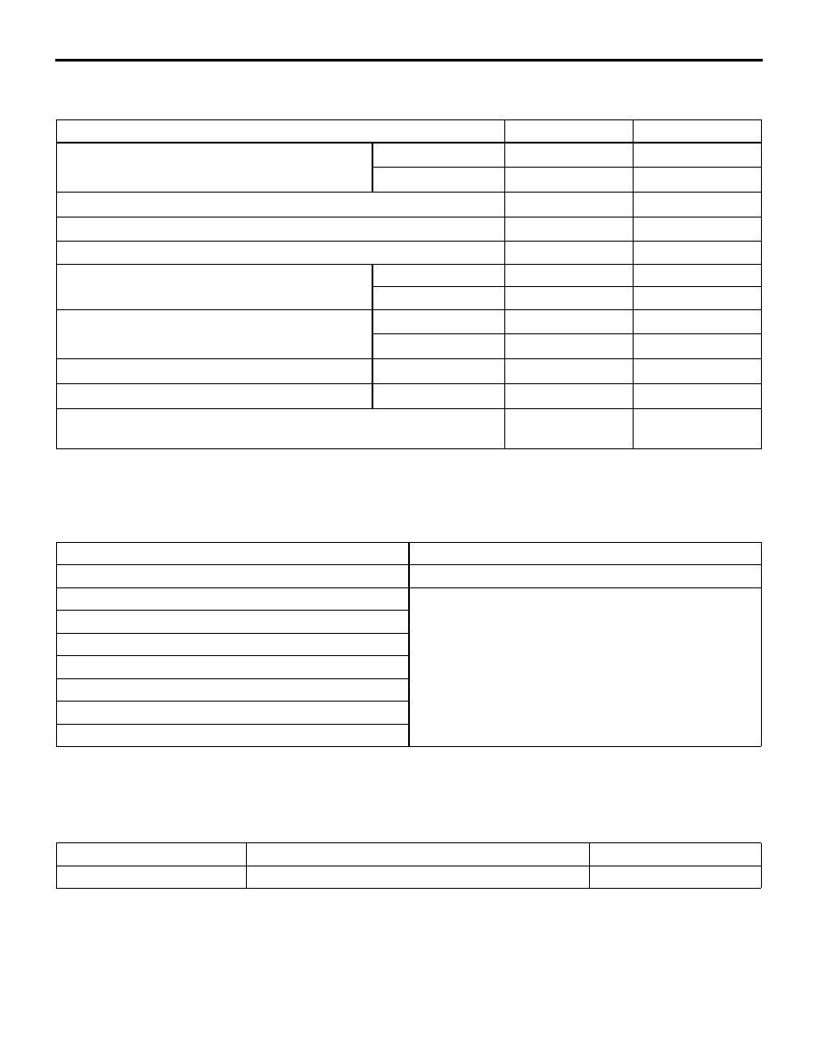
BASIC BRAKE SYSTEM
35A-3
SERVICE SPECIFICATIONS
M1351000300530
LUBRICANTS
M1351000400377
SEALANT
M1351000500385
Item
Standard value
Limit
Brake pedal height mm
L.H. drive vehicles 150
−
153
−
R.H. drive vehicles 176.2
−
179.2
−
Brake pedal free play mm
3
−
8
−
Brake pedal to floor board clearance mm
100 or more
−
Disc brake pad thickness mm
10.0
2.0
Disc brake disc thickness mm
Front
24.0
22.4
Rear
10.0
8.4
Disc brake disc run-out mm
Front
−
0.04
Rear
−
0.05
Disc brake drag force N
Front/Rear
68 or less
−
Wheel bearing axial play mm
Front/Rear
−
0.05
Brake booster push rod protruding length mm (When applying
negative pressure of 66.7 kPa to the brake booster)
10.15
−
10.40
−
Item
Specified lubricant
Brake fluid
DOT3 or DOT4
Guide pin
Repair kit grease
Lock pin
Guide pin boot inner surface
Lock pin boot inner surface
Piston boot mounting grooves
Brake piston boot inner surface
Guide pin bush inner surface
Item
Specified sealant
Remark
Fitting thread part
3M ATD Part No.8661 or equivalent
Semi-drying sealant