Mitsubishi Outlander (2003+). Manual - part 259


  Index      Mitsubishi     Mitsubishi Outlander - service repair manual 2003 year


Search            


Content   ..  257  258  259  260   ..


Mitsubishi Outlander (2003+). Manual - part 259


ON-VEHICLE SERVICE

BASIC BRAKE SYSTEM

35A-7

BLEEDING

M1351001400400

CAUTION

Use only brake fluid DOT 3 or DOT 4. Never mix 
the specified brake fluid with other fluid as it will 
influence the braking performance significantly.

MASTER CYLINDER BLEEDING
The master cylinder used has no check valve, so if 
bleeding is carried out by the following procedure, 
bleeding of air from the brake pipeline will become 
easier (When brake fluid is not contained in the 
master cylinder).
1. Fill the reserve tank with brake fluid.
2. Keep the brake pedal depressed.

3. Have another person cover the master cylinder 

outlet with a finger.

4. With the outlet still closed, release the brake 

pedal.

5. Repeat steps 2 

 4 three or four times to fill the 

inside of the master cylinder with brake fluid.

BRAKE LINE BLEEDING

Start the engine and bleed the air in the sequence 
shown in the figure.

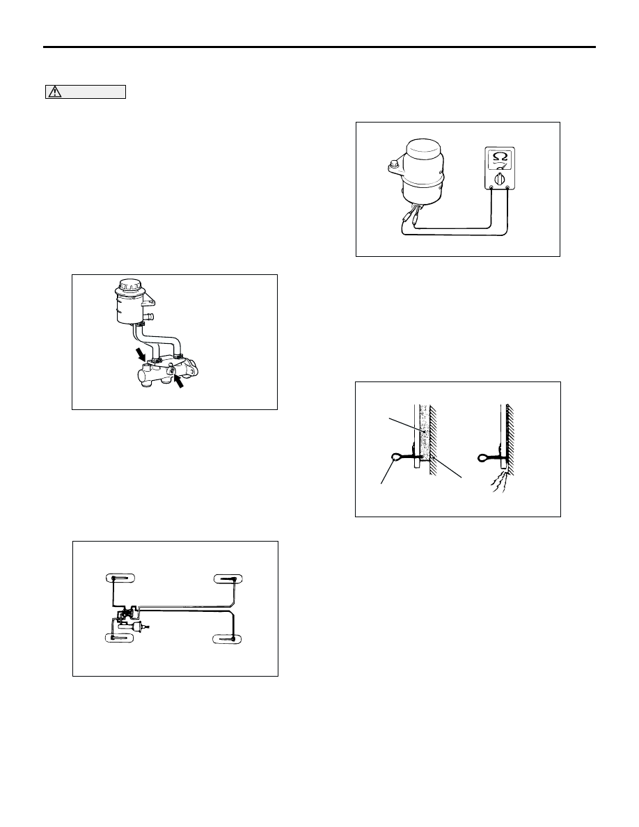
BRAKE FLUID LEVEL SENSOR CHECK

M1351009100351

The brake fluid level sensor is in good condition if 
there is no continuity when the float surface is above 
"MIN" and if there is continuity when the float surface 
is below "MIN".

DISC BRAKE PAD CHECK AND 
REPLACEMENT

M1351002300343

NOTE: 

The brake pads have indicators that contact the 
brake disc when the brake pad thickness becomes 2 
mm, and emit a squealing sound to warn the driver.

AC301227AB

Outlet

Outlet

AC301228AB

4

2

1

3

AC102357

AC000879

When new

When worn

AD

Pad

Wear indicator

Brake
disc

ON-VEHICLE SERVICE

BASIC BRAKE SYSTEM

35A-8

CAUTION

Whenever a pad must be replaced, replace 
both LH and RH wheel pads as a set to 
prevent the vehicle from pulling to one side 
when braking.

If there is a significant difference in the 
thicknesses of the pads on the left and right 
sides, check the sliding condition of the 
piston and slide pins.

1. Check the brake pad thickness through the caliper 

body check port.

Standard value: 10.0 mm
Minimum limit: 2.0 mm

CAUTION

Do not wipe off the special grease that is on the 
lock pin or allow it to contaminate the lock pin.

2. Remove the guide/lock pin bolt. Pivot the caliper 

assembly and hold it with wires.

AC301229AB

<Front>

<Rear>

AC301229AC

<Front>

<Rear>

ON-VEHICLE SERVICE

BASIC BRAKE SYSTEM

35A-9

3. Remove the following parts from caliper support.

(1) Pad assembly or Pad and wear indicator 

assembly 

(2) Pad assembly
(3) Clip
(4) Inner shim
(5) Outer shim

4. In order to measure the brake drag force after pad 

installation, measure the rotary-sliding resistance 
of the hub with the pads removed. For the front 
brakes, refer to 

P.35A-19

. For the rear brakes, 

refer to 

P.35A-24

.

5. Install the pads and caliper assembly, and then 

check the brake drag force. For the front brakes, 
refer to 

P.35A-19

. For the rear brakes, refer to 

P.35A-24

.

AC301230AB

1

1

2

2

3

3

3

3

5

4

5

<Front>

<Rear>

ON-VEHICLE SERVICE

BASIC BRAKE SYSTEM

35A-10

DISC BRAKE ROTOR CHECK

M1351002900367

CAUTION

Disc brakes must be kept within the allowable 
service values in order to maintain normal brake 
operation.
Before turning the brake disc, the following 
conditions should be checked.

BRAKE DISC THICKNESS CHECK

1. Using a micrometer, measure disc thickness at 

eight positions, approximately 45

°

 apart and 10 

mm in from the outer edge of the disc.
Standard value:

<Front> 24.0 mm
<Rear> 10.0 mm

Minimum limit:

<Front> 22.4 mm
<Rear> 8.4 mm

NOTE: Thickness variation (at least 8 positions) 
should not be more than 0.015 mm.

Inspection item

Remark

Scratches, rust, saturated lining materials and wear

If the vehicle is not driven for a long period of 
time, sections of the discs that are not in contact 
with the pads will become rusty, causing noise 
and shuddering.

If grooves and scratches resulting from excessive 
disc wear are not removed prior to installing a new 
pad assembly, there will be inadequate contact 
between the disc and the lining (pad) until the 
pads conform to the disc.

Run-out

Excessive run-out of the discs will increase the pedal 
depression resistance due to piston kick-back.

Change in thickness (parallelism)

If the thickness of the disc changes, this will cause 
pedal pulsation, shuddering and surging.

Inset or warping (flatness)

Overheating and improper handling while servicing 
will cause warping or distortion.

ACX00668


Content   ..  257  258  259  260   ..