Mitsubishi Outlander (2003+). Manual - part 256


  Index      Mitsubishi     Mitsubishi Outlander - service repair manual 2003 year


Search            


Content   ..  254  255  256  257   ..


Mitsubishi Outlander (2003+). Manual - part 256


SHOCK ABSORBER ASSEMBLY

REAR SUSPENSION

34-21

WARNING

Do not use an impact wrench to remove the 
self-locking nut. Vibration of the impact 
wrench will cause special tools (MB991237 
and MB991239) to slip and cause personal 
injury.

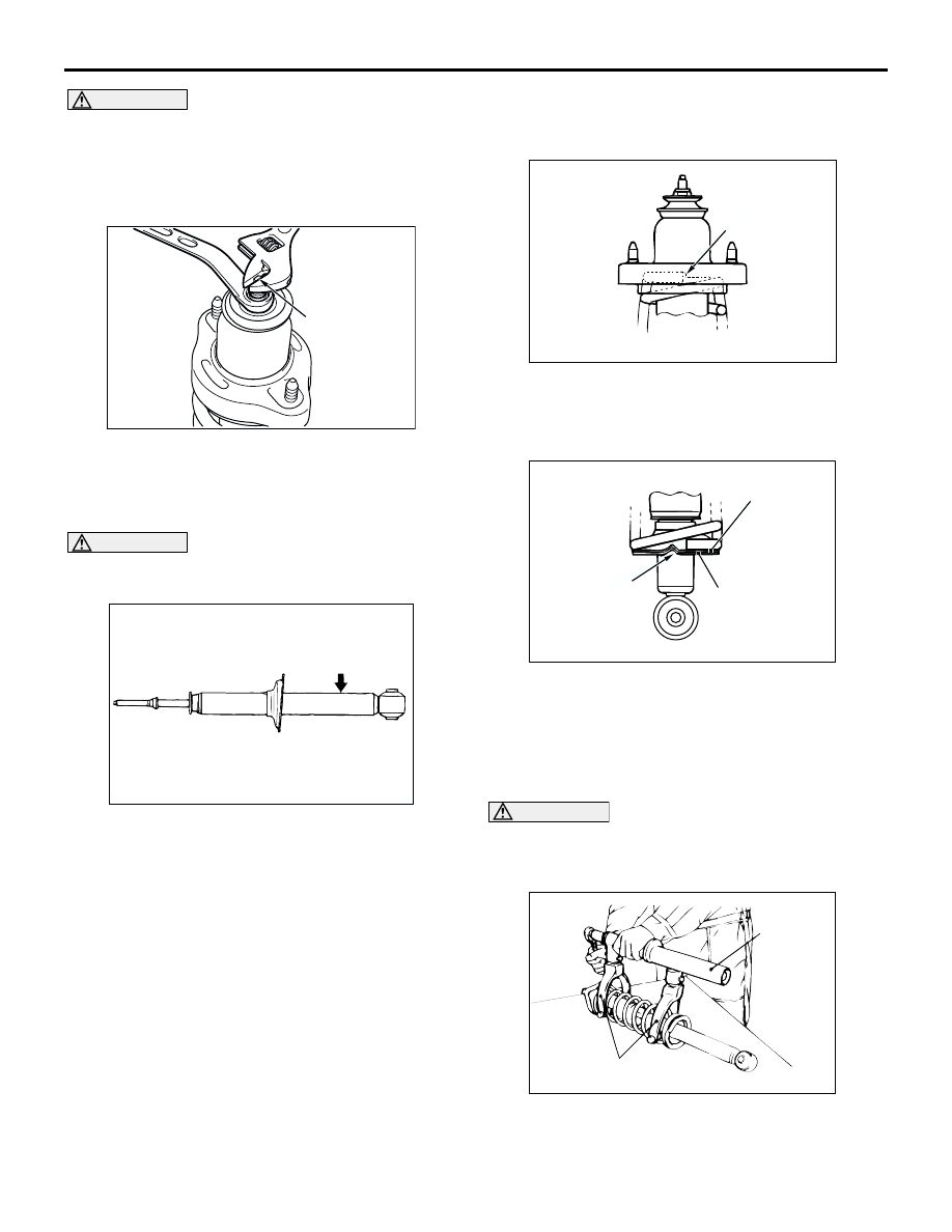
2. While holding the piston rod, remove the 

self-locking nut.

<<B>> SHOCK ABSORBER DISPOSAL

WARNING

Wear goggles when drilling to protect your 
eyes from flying metal debris.

The gas must be discharged from the shock 
absorber before discarding it. Place the shock 
absorber horizontally with its piston rod extended. 
Then drill a hole of approximately 3 mm in diameter 
at the location shown in the illustration and discharge 
the gas.

REASSEMBLY SERVICE POINTS

>>A<< UPPER SPRING PAD/LOWER SPRING 
PAD INSTALLATION

<UPPER SPRING PAD>
Align the stepped section of the spring upper pad 
with the upper end of the coil spring, and install the 
spring upper pad.

<LOWER SPRING PAD>
Align the stepped section of the spring lower pad 
with the stepped section of the spring seat of the 
shock absorber, and install the spring lower pad.

>>B<< COIL SPRING INSTALLATION

CAUTION

Do not use an impact wrench to tighten the bolt 
of special tool spring compressor body 
(MB991237). It will break the special tool.

1. Use following special tools to compress the coil 

spring, and install it to the lower spring pad.

MB991237: Spring Compressor Body

AC102268AC

Piston rod

AC102270 AC

AC304801AC

Spring upper pad
stepped section

AC304800 AB

Spring lower pad

Stepped section

Spring seat

AC001070

MB991237

MB991239

AB

SHOCK ABSORBER ASSEMBLY

REAR SUSPENSION

34-22

MB991239: Arm Set

2. Align the end of the coil spring with the stepped 

section of the lower spring pad.

>>C<< BRACKET ASSEMBLY INSTALLATION

Install the rear shock absorber insulator so that the 
axis of the lower bushing inner pipe of the shock 
absorber and the line between the rear shock 
absorber insulator mounting bolts are straight when 
looking from above.

>>D<< SELF-LOCKING NUT INSTALLATION
1. Temporarily tighten the self-locking nut.

CAUTION

Do not use an impact wrench to tighten the 
self-locking nut, otherwise the self-locking nut 
will be damaged.
2. Remove the special tools, and then tighten the 

self-locking nut to 25 

±

 5 N

m.

AC304802

Lower bushing inner pipe

Rear shock absorber 
insulator mounting bolt

AB

Lower bushing 
inner pipe

STABILIZER BAR

REAR SUSPENSION

34-23

STABILIZER BAR

REMOVAL AND INSTALLATION

M1341003000236

Post-installation Operation

Press the dust cover with your finger to check that there 

are no cracks or damage in the dust cover.

AC301224

AB

12 ± 2 N·m

39 ± 5 N·m

1

2

3

2

4 <4WD>

3

1

39 ± 5 N·m

39 ± 5 N·m

12 ± 2 N·m

1

Specified grease:
     Multipurpose grease SAE J310, 
     NLGI No.2 or equivalent

4 <2WD>

Removal steps

1.

Stabilizer link

>>A<<

2.

Fixture

>>A<<

3.

Bushing

>>A<<

4.

Stabilizer bar

Removal steps (Continued)

STABILIZER BAR

REAR SUSPENSION

34-24

INSTALLATION SERVICE POINT

>>A<< STABILIZER BAR/BUSHING/FIXTURE 
INSTALLATION

Install the stabilizer bar, the bushings and the fixtures 
so that the stoppers come inboard of the bushings. 

INSPECTION

M1341001400272

Check the bushings for wear and deterioration.

Check the stabilizer bar for deterioration or 
damage.

Check all bolts for condition and straightness.

STABILIZER LINK BALL JOINT TURNING 
TORQUE CHECK

1. After shaking the ball joint stud several times, 

install the nut to the stud and use special tool 
preload socket (MB990326) to measure the 
turning torque of the ball joint.

Standard value: 1.7 

 3.1 N

m

2. If the measured value exceeds the standard 

value, replace the stabilizer link.

3. If the measured value is lower than the standard 

value, check that the ball joint turns smoothly 
without excessive play. If so, it is possible to 
re-use that ball joint.

STABILIZER LINK BALL JOINT DUST COVER 
CHECK
1. Check the dust cover for cracks or damage by 

pushing it with your finger.

2. If the dust cover is cracked or damaged, replace 

the stabilizer link.
NOTE: Cracks or damage of the dust cover may 
cause damage to the ball joint. When it is 
damaged during service work, replace the dust 
cover (Refer to 

P.34-24

).

STABILIZER LINK BALL JOINT DUST 
COVER REPLACEMENT

M1341010900220

Only when the dust cover is damaged accidentally 
during service work, replace the dust cover as 
follows:

1. Remove the clip ring and the dust cover.
2. Apply specified grease to the inside of a new dust 

cover.

Specified grease: Multipurpose grease SAE 
J310, NLGI No.2 or equivalent

3. Wrap plastic tape around the stabilizer link stud, 

and then install the dust cover to the stabilizer 
link.

4. Secure the dust cover by the clip ring. 
5. Check the dust cover for cracks or damage by 

pushing it with finger.

AC200960AC

Outside of vehicle

Bushing (LH)

Fixture (LH)

Stopper

AC001129

MB990326

AB

AC006188AB

Clip ring


Content   ..  254  255  256  257   ..