Mitsubishi Outlander (2003+). Manual - part 218


  Index      Mitsubishi     Mitsubishi Outlander - service repair manual 2003 year


Search            


Content   ..  216  217  218  219   ..


Mitsubishi Outlander (2003+). Manual - part 218


TRANSMISSION CONTROL

AUTOMATIC TRANSMISSION (FF)

23A-167

DISASSEMBLY SERVICE POINT

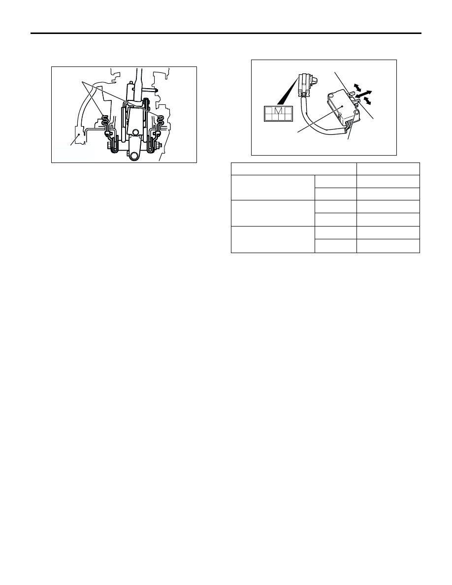
<<A>> PRE-DISASEMBLY CHECK

If the collision energy absorbing mechanism has 
already operated and the part A in the illustration is 
deformed, replace the selector lever assembly.

INSPECTION

M1231006900218

AC103620AC

A

Shift switch 
assembly

Switch position

Terminal NO.

Select switch

ON

 4

OFF

 2

Shift switch (up)

ON

 6

OFF

Shift switch (down)

ON

 5

OFF

1
3 4 5 6

2

AC103390AC

Shift switch (up) 

Select switch

Shift switch
(down) 

Shift switch 
assembly

OFF

ON

OFF

ON

OFF

ON

A/T KEY INTERLOCK AND SHIFT LOCK MECHANISMS

AUTOMATIC TRANSMISSION (FF)

23A-168

A/T KEY INTERLOCK AND SHIFT LOCK MECHANISMS

REMOVAL AND INSTALLATION 
<VEHICLES WITH LHD>

M1232001200507

CAUTION

When removing and installing the shift lock cable unit, be careful not to hit the SRS-ECU.

Pre-removal Operation 

Instrument Lower Panel Removal (Refer to GROUP 52A, 

Instrument Panel Assembly 

P.52A-2

.)

Lower Column Cover Removal (Refer to GROUP 37, 

Steering Shaft 

P.37A-18

.)

Post-installation Operation 

Instrument Lower Panel Installation (Refer to GROUP 

52A, Instrument Panel Assembly 

P.52A-2

.)

Lower Column Cover Installation (Refer to GROUP 37, 

Steering Shaft 

P.37A-18

.)

Key Interlock and Shift Lock Mechanism Check (Refer to 

P.23A-159

.)

AC202709AI

N

6

1

5.0 ± 1.0 N·m

5

4

3

2

Shift lock cable unit removal 
steps

1.

Cover

2.

Slider

3.

Key interlock cable connection 
(steering lock cylinder side)

4.

Split pin

5.

Shift lock cable connection (brake 
pedal side)

>>A<<

6.

Shift lock cable unit

Shift lock cable unit removal 
steps (Continued)

A/T KEY INTERLOCK AND SHIFT LOCK MECHANISMS

AUTOMATIC TRANSMISSION (FF)

23A-169

INSTALLATION SERVICE POINT

>>A<< SHIFT LOCK CABLE UNIT (SELECTOR 
LEVER SIDE) INSTALLATION
1. Selector lever to P position.
2. Turn the ignition switch to LOCK (OFF) position.

3. Install the shift lock cable unit rod to the selector 

lever assembly lock cam, and tighten the shift lock 
cable unit installation bolt to the specified torque.

Tightening torque: 5.0 

±

 1.0 N

m

4. Check the selector lever operation.(Refer to 

P.23A-158

)

AC203163AC

Lock cam

Shift lock
cable unit

A/T KEY INTERLOCK AND SHIFT LOCK MECHANISMS

AUTOMATIC TRANSMISSION (FF)

23A-170

REMOVAL AND INSTALLATION 
<VEHICLES WITH RHD>

M1232001200518

CAUTION

When removing and installing the shift lock cable unit, be careful not to hit it against the SRS-ECU.

Pre-removal and Post-installation Operation

Selector Lever Assembly Removal and Installation (Refer 

to 

P.23A-163

.)

Instrument Lower Panel Removal and Installation (Refer 

to GROUP 52A 

 Instrument Panel 

P.52A-8

.)

Lower Column Cover Removal and Installation (Refer to 

GROUP 37A 

 Steering Shaft 

P.37A-18

.)

Key Interlock and Shift Lock Mechanisms Check <after 

installation only> (Refer to 

P.23A-159

.)

AC103061

1

2

3

5.0 ± 1.0 N·m

AB

Removal steps

<<A>>

>>B<<

1.

Key interlock cable connection 
(steering lock cylinder side)

Footrest

2.

Shift lock cable connection (brake 
pedal side)

>>A<<

3.

Shift lock cable unit

Removal steps (Continued)


Content   ..  216  217  218  219   ..