Mitsubishi Outlander (2003+). Manual - part 217
TRANSMISSION CONTROL
AUTOMATIC TRANSMISSION (FF)
23A-163
REMOVAL AND INSTALLATION
<VEHICLES WITH RHD>
M1231006600411
CAUTION
When removing and installing the transmission control cable and shift lock cable unit, be careful not
to hit the SRS-ECU.
Pre-removal and Post-installation Operation
•
Instrument Panel Centre Console Removal and
Installation (Refer to GROUP 52A
−
Instrument Panel
assembly
AC103060
1
2
3
4
5
6
AC
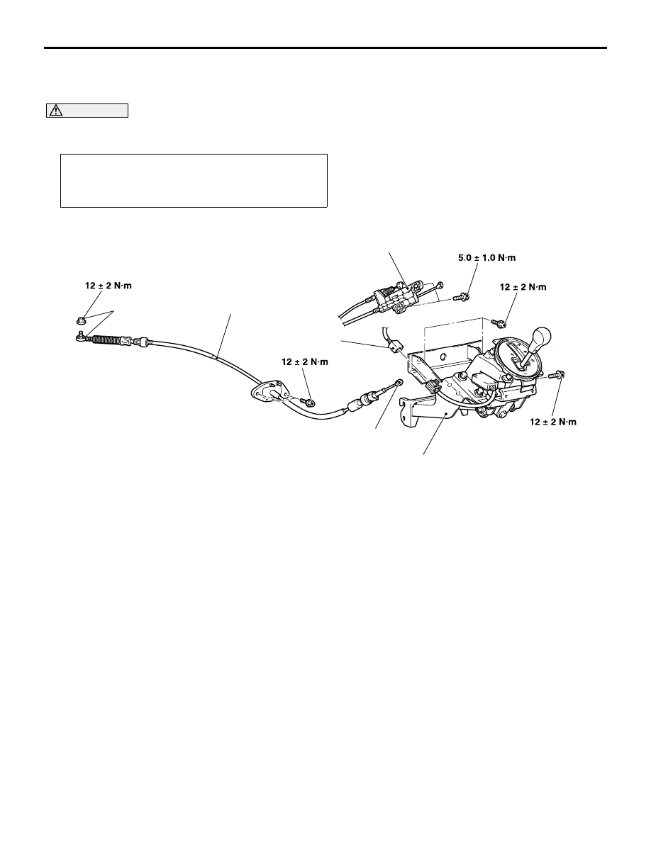
Selector lever assembly and
transmission control cable
assembly removal steps
•
Footrest
>>B<<
1.
Transmission control cable
connection (Transmission side)
>>A<<
2.
Shift lock cable unit connection
3.
Transmission control cable
connection (shift lever side)
4.
Shift switch connector
5.
Selector lever assembly
•
Air cleaner (Refer to GROUP 15 -
Air cleaner
.)
•
Battery and Battery tray
•
SRS-ECU (Refer to GROUP 52B -
SRS air bag control unit
.)
6.
Transmission control cable
assembly
Selector lever assembly and
transmission control cable
assembly removal steps