Mitsubishi Outlander (2003+). Manual - part 216
ON-VEHICLE SERVICE
AUTOMATIC TRANSMISSION (FF)
23A-159
KEY INTERLOCK AND SHIFT LOCK
MECHANISM CHECK
M1232003100238
1. Carry out the following check.
2. If the above operations do not occur correctly,
adjust the shift lock cable unit by the following
procedure.
(1) Remove the front floor console (Refer to
GROUP 52A
−
Floor Console Assembly
) <LHD>.
Remove the instrument panel center console
(Refer to GROUP 52A
−
Instrument Panel
) <RHD>.
(2) Move the selector lever to P position.
(3) Turn the ignition key to LOCK (OFF) position.
Key interlock side
Inspection
procedure
Inspection conditions
Check details (normal condition)
1
Brake pedal:
Depressed
Ignition key position:
LOCK (OFF) or pulled out
The selector lever push button cannot be
pushed, and the selector lever should not
be moved from P position.
2
Ignition key position:
Other than above
The selector lever push button can be
pushed, and the selector lever can be
moved from P position.
3
Selector lever position: Other than P position
The ignition key cannot turned to LOCK
(OFF) position.
4
Selector lever position: P position
The ignition key can be turned to LOCK
(OFF) position.
shift lock side
Inspection
procedure
Inspection conditions
Check details (normal condition)
1
Ignition switch
position: ACC
Brake pedal:
Depressed
The selector lever push button can be pushed, and the
selector lever can be moved from P position.
2
Brake pedal:
Not depressed
The selector lever push button cannot be pushed, and
the selector lever should not be moved from P position.
3
The selector lever push button can be pushed, and the
selector lever can be moved from R position to P
position.
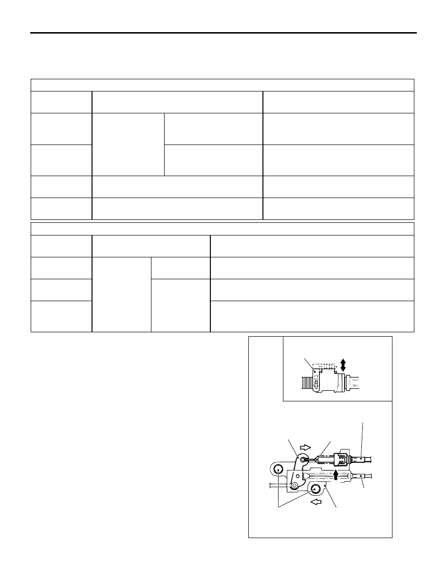
AC000004
B
C
A
View A
Lock guide
AC
Lock released
Locked
Key interlock cable
Cap
Lever
Shift lock cable
Shift lock
cable unit
Fixing bolt