Mitsubishi Outlander (2003+). Manual - part 10
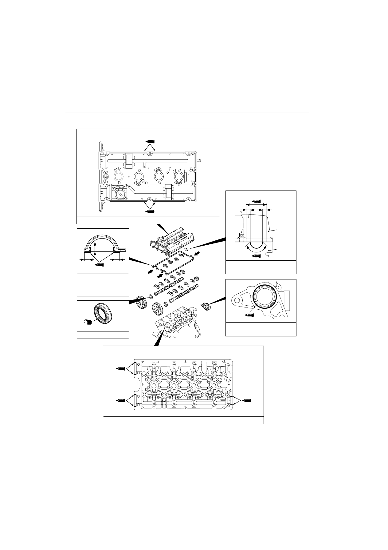
CAMSHAFT AND VALVE STEM SEAL
ENGINE MECHANICAL
11A-17
LUBRICATION AND SEALING POINTS
<The bottom view of the rocker cover>
Sealant: MITSUBISHI GENUINE PART MD970389 or equivalent
Engine oil
(Lip section)
10 mm
10 mm
10 mm
<View A>
Sealant: 3M ATD Part No.8660
or equivalent
10 mm
10 mm
Rocker
cover
Cylinder
head
φ
3 mm
AC300541
A
A
A
Sealant:
MITSUBISHI GENUINE
PART MD970389 or
equivalent
Sealant: MITSUBISHI GENUINE
PART MD970389 or equivalent
Sealant: MITSUBISHI GENUINE PART MD970389 or equivalent
<Top view of cylinder head>