Mitsubishi Montero Sport (2004+). Manual - part 594


  Index      Mitsubishi     Mitsubishi Montero Sport - service repair manual 2004 year


Search            


Content   ..  592  593  594  595   ..


Mitsubishi Montero Sport (2004+). Manual - part 594


GENERAL DESCRIPTION

TSB Revision

HEATER, AIR CONDITIONING AND VENTILATION

55-3

GENERAL DESCRIPTION

M1551000100091

The heater system uses a two-way-flow full-air-mix 
system that features high performance and low oper-
ating noise. It includes an independent face air blow-
ing function and a cool air bypass function. The air 
conditioning (A/C) system is basically the same as 
the conventional system, but a new refrigerant sys-
tem has been adopted as a response to restrictions 
on the use of chlorofluorocarbons.

SAFETY PRECAUTIONS

WARNING

Wear safety goggles when servicing the 
refrigeration system to prevent severe dam-
age to hands.

Because R-134a refrigerant is a hydro fluorocarbon 
(HFC) which contains hydrogen atoms in place of 
chlorine atoms, it will not cause damage to the ozone 
layer. Ozone filters out harmful radiation from the 
sun. To assist in protecting the ozone layer, Mitsub-
ishi Motors Corporation recommends an R-134a 
refrigerant recycling device. Refrigerant R-134a is 
transparent and colorless in both the liquid and vapor 
state. Since it has a boiling point of 
−29.8°C (−21.6°F) at atmospheric pressure, it will be 

a vapor at all normal temperatures and pressures. 
The vapor is heavier than air, non-flammable, and 
non-explosive. The following precautions must be 
observed when handling R-134a.

WARNING

Do not heat R-134a above 40

°

C (104

°

F) or it 

may catch fire and explode.

R-134a evaporates so rapidly at normal atmospheric 
pressures and temperatures that it tends to freeze 
anything it contacts. For this reason, extreme care 
must be taken to prevent any liquid refrigerant from 
contacting the skin and especially the eyes. Always 
wear safety goggles when servicing the refrigeration 
part of the A/C system. Keep a bottle of sterile min-
eral oil handy when working on the refrigeration sys-
tem.

1. Should any liquid refrigerant get into the eyes, use 

a few drops of mineral oil to wash them out. 
R-134a is rapidly absorbed by the oil.

2. Next splash the eyes with plenty of cold water.
3. Call your doctor immediately even though irritation 

has ceased after treatment.

CAUTION

Keep R-134a containers upright when charging 
the system.
In most instances, moderate heat is required to bring 
the pressure of the refrigerant in its container above 
the pressure of the system when charging or adding 
refrigerant. A bucket or large pan of hot water not 
over 40

°C (104°F) is all the heat required for this pur-

pose. Do not heat the refrigerant container with a 
blow torch or any other means that would raise tem-
perature and pressure above this temperature. Do 
not weld or steam clean on or near the system com-
ponents or refrigerant lines.
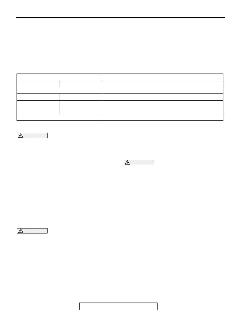
ITEM

SPECIFICATION

Heater unit

Type

Two-way-flow full-air-mix system

Heater control assembly

Dial type

Compressor

Model

Scroll type <MSC105C>

Dual pressure switch 
kPa (psi)

High-pressure switch ON to OFF: 2,942 (426.7), OFF to ON: 2,354 (341.4)
Low-pressure switch ON to OFF: 196 (28.4), OFF to ON: 221 (32.1)

Refrigerant and quantity g (oz)

R-134a (HFC-134a), Approximately 650 

− 680 (23 − 24)

GENERAL DESCRIPTION

TSB Revision

HEATER, AIR CONDITIONING AND VENTILATION

55-4

WARNING

The leak detector for R-134a should be used 
to check for refrigerant gas leaks.

CAUTION

Do not allow liquid refrigerant to touch bright 
metal or it will be stained.
When metering R-134a into the refrigeration system 
keep the supply tank or cans in an upright position. If 
the refrigerant container is on its side or upside 
down, liquid refrigerant will enter the system and 
damage the compressor. Refrigerant will tarnish 
bright metal and chrome surfaces, and in combina-
tion with moisture can severely corrode all metal sur-
faces.

OPERATION

When the air conditioning is working under low loads 
(e.g. in winter), the PCM controls the A/C compres-
sor, condenser fan and idle-up speed more effec-
tively, resulting in good fuel economy and quiet 
engine operation. In addition, the condenser fan will 
always run for five minutes as initial check after the 
battery is reconnected.

.

Condenser fan control

• For the operation of each fan, refer to GROUP14, 

Diagnosis 

P.14-2

.

.

Compressor and radiator fan control
When operating the air conditioning switch

• The automatic compressor controller stops the air 

compressor when the air thermo sensor detects a 
temperature of 3.2

°C (38°F) or less. However, if 

the outside air temperature sensor detects a tem-
perature of 10 

− 20°C (50 − 68°F), the controller 

stops the air compressor when the air thermo 
sensor detects 6.2

°C (43°F) or less. Because of 

this control, the compressor can work efficiently 
when the air conditioner is under low load.

• The PCM stops the air compressor when the 

engine coolant temperature sensor detects 115

°C 

(239

°F). In addition, the air compressor stops for 

five seconds when the accelerator position sen-
sor input exceeds 80%. Moreover, the compres-
sor stops during engine start and low engine 
speed. Because of this control, the engine load 
can be reduced.

• The dual pressure switch turns OFF when the 

refrigerant pressure becomes excessively high or 
low, thus protecting the compressor circuit. (See 
Table below.)

• When these two sensors are all activated, the 

dual pressure switch is ON, and the ignition 
switch, the blower switch, and the air conditioning 
switch are ON, the A/C compressor clutch relay is 
energized.

When operating the air outlet changeover control 
knob

• When the air outlet changeover control knob is 

moved to "DEFROSTER" or 
"DEFROSTER/FOOT" position, the micro switch, 
which is connected in series to the air condition-
ing switch, is turned on. The other compressor 
control than the above is the same as that when 
operating the air conditioning switch.

MANUAL A/C DIAGNOSIS

TSB Revision

HEATER, AIR CONDITIONING AND VENTILATION

55-5

A/C Compressor Clutch Relay ON Conditions

.

MANUAL A/C DIAGNOSIS

INTRODUCTION TO HEATER, AIR CONDITIONING AND VENTILATION DIAGNOSIS

M1552012200258

With this system, after the outside air or inside air is 
taken in through the damper, it is fed to the evapora-
tor by the blower fan and motor and cooled. The air 
cooled by the air mix damper is mixed appropriately 
with the warmed air to achieve a comfortable temper-
ature. If the A/C does not operate or the cooled air is 
not discharged, the machine components or relay 
may be faulty.

HEATER, AIR CONDITIONING AND VENTILATION DIAGNOSTIC TROUBLESHOOTING 
STRATEGY

M1552009600278

CAUTION

If the condenser fan does not run as the air con-
ditioning is on under low load, disconnect the 
negative battery cable for a moment and then 
reconnect it. Then a trouble symptom can be 
checked for five minutes after the condenser 
starts running.
Use these steps to plan your diagnostic strategy. If 
you follow them carefully, you will be sure that you 
have exhausted most of the possible ways to find a 
heater, air conditioning and ventilation fault.

1. Gather information from the customer.
2. Verify that the condition described by the 

customer exists.

3. Find the malfunction by following the Symptom 

Chart.

4. Verify malfunction is eliminated.

Ignition switch (IG2)

ON

Remarks 
(1) A/C compressor clutch relay is 
de-energized when any one switch, 
sensor or control unit shown on the left 
turns off (HI). 
(2) *: Automatic compressor controller 
and PCM judges from input signals from 
the sensors.

Blower switch

ON

Air conditioning switch or micro switch

ON

Air thermo sensor

*

Outside air temperature sensor

*

Engine coolant temperature sensor

*

Dual pressure switch 

Low-pressure side 221 kPa 
(32.1 psi) or higher

ON

High-pressure side 
2,942kPa (426.7 psi) or 
below

ON

A/C compressor clutch relay driving transistor (within 
powertrain control module)

ON

MANUAL A/C DIAGNOSIS

TSB Revision

HEATER, AIR CONDITIONING AND VENTILATION

55-6

SYMPTOM CHART

M1552009900503

NOTE: For symptoms marked with an asterisk the condenser fan might not operate when there is an air con-
ditioning low load from the air conditioning condenser control, so remove the negative battery terminal and 
then check the symptoms 5 minutes after initial start control reconnection.

SYMPTOMS

INSPECTION 
PROCEDURE

REFERENCE 
PAGE

When the ignition switch is ON, the A/C does not operate.

1

P.55-7

When the air outlet changeover control knob is moved to DEFROSTER 
or DEFROSTER/FOOT position, the A/C or the inside/outside air 
changeover damper motor does not operate.

2

P.55-10

When the A/C is operating, temperature inside the passenger 
compartment does not decrease (cool air is not emitted).

3

P.55-11

Blower fan and motor does not operate.

4

P.55-12

Blower fan and motor does not stop operating.

5

P.55-14

When the A/C is operating condenser fan does not operate.*

6

P.55-16

Even when the rear heater switch is pressed, the blower fan does not 
turn.

7

P.55-18

The rear heater air volume cannot be controlled in two steps.

8

P.55-20

When the Heater Control Knob is Set to the "MAX COOL" Position, the 
Air-Conditioning does not Cool Sufficiently.

9

P.55-21

Warm Air does not Go Out From the Air Outlets.

10

P.55-23


Content   ..  592  593  594  595   ..