Mitsubishi Montero Sport (2004+). Manual - part 595


  Index      Mitsubishi     Mitsubishi Montero Sport - service repair manual 2004 year


Search            


Content   ..  593  594  595  596   ..


Mitsubishi Montero Sport (2004+). Manual - part 595


MANUAL A/C DIAGNOSIS

TSB Revision

HEATER, AIR CONDITIONING AND VENTILATION

55-7

SYMPTOM PROCEDURES

INSPECTION PROCEDURE 1: When the Ignition Switch is ON, the A/C does not Operate.

DIAGNOSIS

STEP 1. Check for refrigerant leaks.
Q: Is the refrigerant leaking?

YES : Repair the leak. Then go to Step 10.
NO :  Go to Step 2.

STEP 2. Check for excessive refrigerant.
Q: Is the refrigerant in good condition?

YES : Go to Step 3.
NO :  Use the refrigerant recovery station to remove all of 

the refrigerant, and then calculate the amount of the 
refrigerant and charge it. Then go to Step 10.

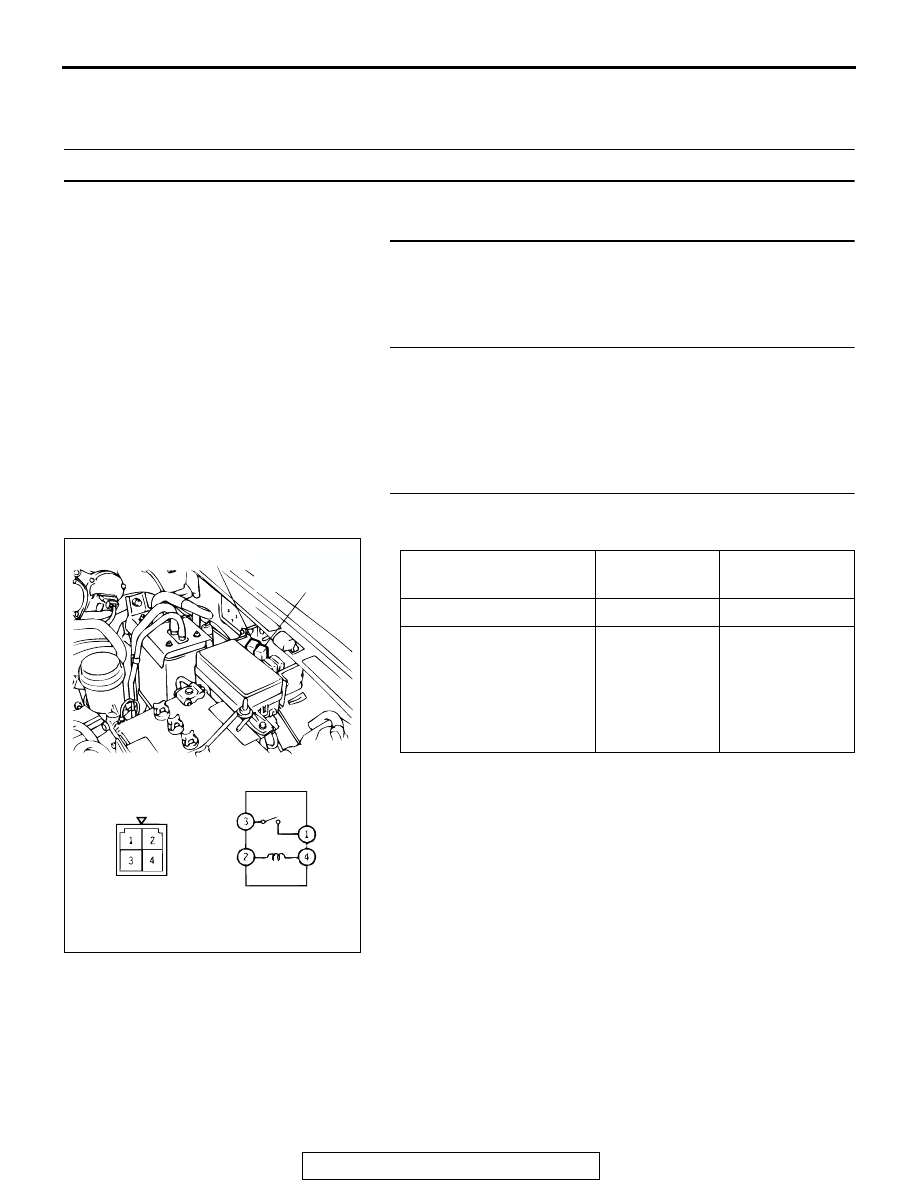
STEP 3. Check the A/C compressor clutch relay continuity.

Remove the A/C compressor clutch relay and continuity check. 

Q: Is the A/C compressor clutch relay in good condition?

YES : Go to Step 4.
NO :  Replace. Then go to Step 10.

BATTERY VOLTAGE

TESTER 
CONNECTION

SPECIFIED 
CONDITION

Not applied

− 3

Open circuit

• Connect terminal 2 to 

the positive battery 
terminal

• Connect terminal 4 to 

the negative battery 
terminal

− 3

Less than 2 
ohms

AC002843AC

CONDENSER FAN 

MOTOR RELAY

A/C

COMPRESSOR 

CLUTCH RELAY

MANUAL A/C DIAGNOSIS

TSB Revision

HEATER, AIR CONDITIONING AND VENTILATION

55-8

STEP 4. Check the A/C compressor clutch operation.

Connect the battery (+) terminal to the compressor A/C com-
pressor clutch connector terminal 3 and ground the battery (-) 
terminal to the body of the compressor. 
Q: Can the sound of the A/C compressor clutch (click) be 

heard?
YES : 
Go to Step 5.
NO :  Replace. Then go to Step 10.

STEP 5. Check the dual pressure switch operation.

(1) Remove the dual pressure switch connector and connect 

the high/low pressure side terminals located on the harness 

side as shown in the illustration.

(2) Install a gauge manifold to the high-pressure side service 

valve of the refrigerant line. (Refer to 

P.55-29

.)

(3) When the high/low pressure sides of the dual pressure 

switch are at operation pressure (ON) and the resistance is 
less than two ohms between the respective terminals, then 
the condition is normal. If open loop, replace the switch.

Q: Is the dual pressure switch operating properly?

YES : Go to Step 6.
NO :  Replace the switch. Then go to Step 10.

STEP 6. Check the A/C switch continuity.

Remove the A/C switch and check the continuity.

Q: Is there continuity at the A/C switch?

YES : Go to Step 7.
NO :  Replace. Then go to Step 10.

AC002842

A/C COMPRESSOR CLUTCH

CONNECTOR

AC

ITEM

DUAL PRESSURE SWITCH

FROM OFF TO 
ON

FROM ON TO 
OFF

Low-pressure side kPa 
(psi)

221 (32.1)

196 (28.4)

High-pressure side kPa 
(psi)

2,354 (341.4)

2,942 (426.7)

A003021

HIGH/LOW
PRESSURE SIDE

LOW-PRESSURE
SIDE

HIGH-PRESSURE
SIDE

ON

OFF

ON

OFF

AB

SWITCH 
POSITION

TESTER 
CONNECTION 

SPECIFIED 
CONDITION

At the OFF 
position

− 4

Open circuit

At the ON position 1 

− 4

Less than 2 ohms

AC002848AB

OFF

ON

MANUAL A/C DIAGNOSIS

TSB Revision

HEATER, AIR CONDITIONING AND VENTILATION

55-9

STEP 7. Check the blower switch continuity.

Remove the blower switch and check continuity.

Q: Is there continuity at the blower switch?

YES : Go to Step 8.
NO :  Replace. Then go to Step 10.

STEP 8. Measure the automatic compressor controller 
terminal voltage.

Refer to 

P.55-25

.

Q: Is the automatic compressor controller terminal voltage 

correct?
YES : 
Go to Step 9.
NO :  Replace. Then go to Step 10.

STEP 9. Measure the powertrain control module terminal 
voltage.

Refer to GROUP 13A, Diagnosis 

− Check at the Powertrain 

Control Module (PCM) 

P.13A-856

Q: Is the terminal voltage correct?

YES : Go to Step 10.
NO :  Replace. Then go to Step 10.

STEP 10. Retest the system.
Q: Is the A/C operating properly?

YES : The procedure is complete. (If no malfunctions are 

found in all steps, an intermittent malfunction is 
suspected. Refer to GROUP 00, How to Use 
Troubleshooting/Inspection Service Points 

− How to 

Cope with Intermittent Malfunction 

P.00-7

.)

NO :  Go to Step 1.

SWITCH 
POSITION

TESTER 
CONNECTION 

SPECIFIED 
CONDITION

At the "OFF" 
position

− 8

− 5

− 5

− 6

− 7

Open circuit

At the "LO" position 3 

− 5

− 8

Less than 2 ohms

At the "ML" position 5 

− 6

− 8

Less than 2 ohms

At the "MH" 
position

− 5

− 8

Less than 2 ohms

At the "HI" position 5 

− 7

− 8

Less than 2 ohms

AC002851AB

MANUAL A/C DIAGNOSIS

TSB Revision

HEATER, AIR CONDITIONING AND VENTILATION

55-10

INSPECTION PROCEDURE 2: When the Air Outlet Changeover Control Knob is Moved to Defroster or 
Defroster/foot Position, the Air Conditioning or the Inside/outside Air Changeover Damper Motor 
does not Operate.

DIAGNOSIS

STEP 1. Check the defroster switch continuity.

Q: Is the defroster switch in good condition?

YES : Go to Step 2.
NO :  Replace. Then go to Step 2.

STEP 2. Check each A/C part.
Q: Does A/C operate normally?

YES : The procedure is complete. (If no malfunctions are 

not found in all steps, an intermittent malfunction is 
suspected. Refer to GROUP 00, How to Use 
Troubleshooting/Inspection Service Points 

− How to 

Cope with Intermittent Malfunction 

P.00-7

.)

NO :  Go to Inspection Procedure 1.

AIR OUTLET 
CHANGEOVER 
CONTROL KNOB 
POSITION

TESTER 
CONNECTION 

SPECIFIED 
CONDITION

DEFROSTER, 
DEFROSTER/FOOT

− 3

Less than 2 ohms

OTHER POSITION

− 3

Open circuit

AC002852AB


Content   ..  593  594  595  596   ..