Mitsubishi Montero Sport (2004+). Manual - part 568


  Index      Mitsubishi     Mitsubishi Montero Sport - service repair manual 2004 year


Search            


Content   ..  566  567  568  569   ..


Mitsubishi Montero Sport (2004+). Manual - part 568


ANTENNA

TSB Revision

CHASSIS ELECTRICAL

54-259

REMOVAL SERVICE POINT

.

<<A>> MAST ANTENNA OR MOTOR ANTENNA ASSEMBLY 
REMOVAL
To make installation easy, tie a string on the feeder cable of the 
mast antenna or motor antenna assembly and pull.

INSPECTION

M1543019501608

MOTOR ANTENNA CHECK

Disconnect the antenna motor-ECU connector. Check that the 
antenna extends when the positive terminal of the battery is 
connected to terminal number 1 and the negative terminal of 
the battery is connected to terminal number 2. Check that the 
antenna retracts when the connection is reversed.

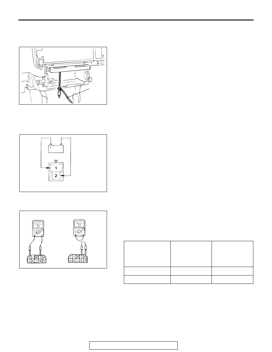
ANTENNA MOTOR-ECU CHECK

1. Remove the antenna motor-ECU mounting bolts.
2. Operate the radio switch when the ignition switch is turned 

to the "ACC" or "ON" position. Measure the voltage between 
the terminals while the antenna is attempting to extend or 
retract.

AC002829

STRING

AB

AC002830 AB

ANTENNA 
OPERATION 
DIRECTION

TERMINAL NO. 
TO BE 
CONNECTED 
TO BATTERY

SPECIFIED 
CONDITION

While lowering

− 3

10 

− 13 volts

While rising

− 3

10 

− 13 volts

AC002813

AC

ANTENNA 
RETRACT

ANTENNA

EXTEND

ANTENNA

TSB Revision

CHASSIS ELECTRICAL

54-260

GLASS ANTENNA CHECK

1. Wrap an aluminum foil around the tester probe a shown.

CAUTION

Be careful not to damage the print wire.
2. Check continuity while pressing the aluminum foil along the 

antenna print wire.

ANTENNA POLE REPLACEMENT

M1544000900170

1. Remove the ring nut.

2. After setting the ignition switch to the "ACC" or "ON," turn 

the radio switch on. Extend the antenna pole and remove it 
together with the rack cable.

3. Pull the antenna out the farthest end.

NOTE: If the motor end side of the rack cable is bent, 
straighten it out.

4. Face the teeth side of the rack cable toward the engine 

compartment, and feed the rack cable into the motor 
assembly.

ACX01954 AB

TESTER PROBE

ALUMINUM FOIL

PRINT WIRE

ACX01953 AB

RING NUT

ANTENNA POLE

ACX01949 AB

RACK CABLE

ANTENNA POLE

ACX01950

RACK CABLE

RACK CABLE 
TEETH

ENGINE 
COMPARTMENT 
SIDE

AB

REAR WINDOW DEFOGGER

TSB Revision

CHASSIS ELECTRICAL

54-261

5. Turn the teeth side of the rack cable toward the front of the 

vehicle (90 degree angle to the right), and engage the rack 
cable with the motor gears.

6. Pull lightly on the rack cable. If there is no resistance and it 

comes out, it is not engaged with the motor gears. Check 
that the end of the rack gear is not bent again, and then 
repeat steps (3) and (4) above again.

7. Set up the antenna pole vertically, and turn the radio off to 

wind in the rack cable. The antenna pole will be pulled into 
the motor antenna as the rack cable is wound in.

8. After tightening the ring nut, turn the radio on and off and 

check the operation of the antenna pole.

REAR WINDOW DEFOGGER

ON-VEHICLE SERVICE

PRINTED-HEATER LINES CHECK

M1543001800203

1. Run engine at 2,000 r/min. Check heater element with 

battery at full.

2. Turn "ON" rear window defogger switch. Measure heater 

element voltage with circuit tester at rear window glass 
centre A. Condition is good if it indicates about 6 V.

3. If 12 V is indicated at A, there is a break in the negative 

terminals from A. Move test bar slowly to negative terminal 
to detect where voltage changes suddenly (0V).

4. If 0 V is indicated at A, there is a break in the positive 

terminals from A. Defect where the voltage changes 
suddenly (12 V) in the same method described above.

ACX01952 AC

RACK CABLE

VEHICLE FRONT 
DIRECTION

ACX01951AB

RING NUT

ACX00813

NORMAL CHARACTERISTIC CURVE

ABNORMAL CHARACTERISTIC CURVE

VOLTAGE

A (CENTER POINT)

APPROXIMATELY
                         6 V

NEGATIVE
TERMINAL

PRINTED 
HEATER
LINE

POSITIVE
TERMINAL

NEGATIVE
TERMINAL

PRINTED 
HEATER
LINE

POSITIVE
TERMINAL

OPENCIRCUIT 
POINT

VOLTAGE

AC

REAR WINDOW DEFOGGER

TSB Revision

CHASSIS ELECTRICAL

54-262

REAR WINDOW DEFOGGER SWITCH

 REMOVAL AND INSTALLATION

M1543006200206

INSPECTION

M1543019502690

REAR WINDOW DEFOGGER SWITCH 
CONTINUITY CHECK

AC002833

: Metal clip position

NOTE

1

2

3

AB

REMOVAL STEPS

1.

METER BEZEL ASSEMBLY

2.

SWITCH HOLDER

3.

REAR WINDOW DEFOGGER SWITCH

REMOVAL STEPS (Continued)

SWITCH 
POSITION

TESTER 
CONNECTION

SPECIFIED 
CONDITION

At the "OFF" 
position

3 - 4

Open circuit

At the "ON" 
position

3 - 4

Less than 2 ohms

AC002834

AB


Content   ..  566  567  568  569   ..