Mitsubishi Montero Sport (2004+). Manual - part 569


  Index      Mitsubishi     Mitsubishi Montero Sport - service repair manual 2004 year


Search            


Content   ..  567  568  569  570   ..


Mitsubishi Montero Sport (2004+). Manual - part 569


REAR WINDOW DEFOGGER

TSB Revision

CHASSIS ELECTRICAL

54-263

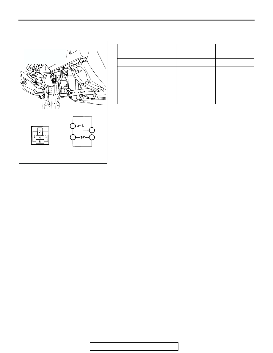
REAR WINDOW DEFOGGER RELAY CONTINUITY 
CHECK

BATTERY 
VOLTAGE

TESTER 
CONNECTION

SPECIFIED 
CONDITION

Not applied

− 3

Open circuit

• Connect terminal 2 to 

the positive battery 
terminal

• Connect terminal 4 to 

the negative battery 
terminal

− 3

Less than 2 
ohms

AC309493

3

2

1

4

REAR WINDOW

DEFOGGER RELAY

AB

THEFT ALARM

TSB Revision

CHASSIS ELECTRICAL

54-264

THEFT ALARM

THEFT-ALARM SYSTEM DIAGNOSIS

INTRODUCTION TO THEFT-ALARM SYSTEM DIAGNOSIS

M1547002200079

Theft-alarm system

When the theft-alarm system has been armed by the 
correct sequence for locking the doors (including the 
transmitter of the keyless entry system) if then a 
door, liftgate or hood is opened in an unauthorized 
way, the horn will sound and headlight flash intermit-
tently for period of 180 seconds, thus providing an 
audible warning signal.

Panic Alarm Function

With the theft alarm function armed, pressing the 
panic button on the keyless entry system transmitter 
causes the theft alarm horn to sound for about 180 
seconds in an attempt to prevent theft. The alarm is 
turned off by pressing any switch on the transmitter.

TROUBLE SYMPTOM CHART

M1543007201194

If a malfunction was found with the input signal 
check, refer to following table and inspect.

SYMPTOM

INSPECTION 
PROCEDURE

REFERENCE 
PAGE

Theft-alarm system is not armed (security indicator light does not 
illuminate).

1.


P.54-265

The horn does not sound when the theft-alarm-system is triggered. 2.


P.54-272

The headlight do not flash when the theft-alarm system is triggered. 3.


P.54-280

The panic alarm function does not work.

4.


P.54-280

SYMPTOM

INSPECTION 
PROCEDURE

REFERENCE 
PAGE

Scan tool MB991958 communication is not possible.

5


P.54-285

The key reminder switch is not sent to the ETACS-ECU.

6.


P.54-293

The hood switch is not input.

7.


P.54-298

The driver's or passenger's door switch is not input.

-

GROUP 42, Door 
− Door Assembly 

P.42-133

The driver's or passenger's door lock actuator switch is not input.

-

GROUP 42, Door 
− Door Assembly 

P.42-133

The liftgate switch is not input.

-

GROUP 42, 
Liftgate 

− Liftgate 

Handle and Latch 

P.42-152

The gate lock key cylinder switch is not input.

-

GROUP 42, 
Liftgate 

− Liftgate 

Handle and Latch 

P.42-152

THEFT ALARM

TSB Revision

CHASSIS ELECTRICAL

54-265

SYMPTOM PROCEDURES

INSPECTION PROCEDURE 1: Theft-alarm System is not Armed (Security Indicator Light does not 
Illuminate). 

Security Indicator Circuit

THEFT ALARM

TSB Revision

CHASSIS ELECTRICAL

54-266

.

CIRCUIT OPERATION
The theft-alarm system will be armed after the doors 
are locked and then the security indicator light has 
illuminated for approximately 18 seconds.

.

TECHNICAL DESCRIPTION (COMMENT)
The ETACS-ECU arms the theft-alarm system 
according to the input signals from the following 
switches:

• Ignition key reminder switch

• Driver's and passenger's door switch

• Door switches

• Driver's and passenger's door key cylinder switch

• Driver's and front passenger's door lock actuator 

switch

• Liftgate switch

• Gate lock key cylinder switch

• Transmitter

If the theft-alarm system is armed normally, the rele-
vant input signal circuit(s), the theft-alarm indicator 
light or the ETACS-ECU may be defective.

.

TROUBLESHOOTING HINTS

• Malfunction of the security indicator

• Malfunction of the ignition key reminder switch

• Malfunction of the driver's or passenger's door 

switch

• Malfunction of the driver's or passenger's door 

lock key cylinder switch 

• Malfunction of the driver's or passenger's door 

lock actuator switch 

• Malfunction of the liftgate switch

• Malfunction of the gate lock key cylinder switch

• Malfunction of the transmitter

• Malfunction of the ETACS-ECU

• Damaged harness wires or connectors

.

AC003431

CONNECTOR: A-54X

A-54X

AC

AC003432AB

CONNECTOR: D-01

JUNCTION BLOCK

(FRONT)

D-01

AC003520

CONNECTORS: D-14, D-26

D-26 (B)

D-14 (B)

AC

JUNCTION BLOCK (REAR)

AC003523

AC

CONNECTOR: C-11

C-11

AC003521

CONNECTOR: C-108

AC

C-108


Content   ..  567  568  569  570   ..