Mitsubishi Montero Sport (2004+). Manual - part 466


  Index      Mitsubishi     Mitsubishi Montero Sport - service repair manual 2004 year


Search            


Content   ..  464  465  466  467   ..


Mitsubishi Montero Sport (2004+). Manual - part 466


DOOR

TSB Revision

BODY

42-119

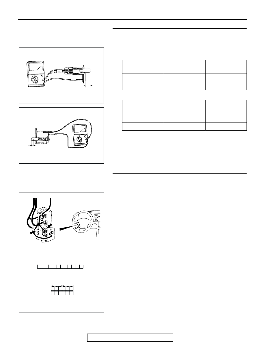
STEP 6. Check the front door switch.
(1) Remove the driver's door or fornt passenger’s door switch 

(Refer to 

P.42-132

).

(2) Follow the table to check the front door switches continuity.

TYPE1

TYPE2

Q: Is the front door switch in good condition?

YES : Go to Step 7 .
NO :  Replace front door switch, then go to Step 11. 

STEP 7. Check ETACS-ECU connector D-11 and D-26 for 
loose, corroded or damaged terminals, or terminals 
pushed back in the connector.
Q: Are ETACS-ECU connector D-11 and D-26 in good 

condition?
YES : 
Go to step 8.
NO :  Repair or replace the damaged components. Refer to 

GROUP 00E 

P.00E-2

, Harness Connector inspection. 

Then go to Step 11.

SWITCH 
POSITION

TESTER 
CONNECTION

SPECIFIED 
CONDITION

Released (ON)

− 2, 1 − 3, 2 − 3 Less than 2 ohms

Depressed (OFF) 1 

− 2, 1 − 3, 2 − 3 Open circuit 

SWITCH 
POSITION

TESTER 
CONNECTION

SPECIFIED 
CONDITION

Released (ON)

− 2 

Less than 2 ohms

Depressed (OFF) 1 

− 2 

Open circuit 

AC003906

TYPE 1

AB

1

2

3

OFF

ON

STROKE

AC003907

TYPE 2

1

2

ON

OFF

STROKE

AB

AC202080

1

4 3 2

5

7 6

8

9

11

12

10

21

22

28 27

24

30

25

31

32

26

29

23

JUNCTION BLOCK (REAR)

CONNECTOR: D-11, D-26

D-11

D-26 (B)

D-11 COMPONENT SIDE

D-26 COMPONENT SIDE

AC

DOOR

TSB Revision

BODY

42-120

STEP 8. Check the harness wire between ETACS-ECU 
connector D-11 (terminal No.9), D-26 (terminal No.26) and 
driver's door switch connectors E-33 (terminal No.2), front 
passenger’s side door switch connector E-46 (terminal 
No.2). 

AC202081

1

4 3 2

5

7 6

8

9

11

12

10

21

22

28 27

24

30

25

31

32

26

29

23

1
8

3

4

5

7 6

10

15

16

14

12

13

11

9

2

JUNCTION BLOCK (REAR)

CONNECTORS: D-11, D-14, D-26

D-11

D-26 (B)

D-11 COMPONENT SIDE

D-26 COMPONENT SIDE

AB

D-14 COMPONENT SIDE

D-14 (B)

AC202082

2 1

8

19

7

6

5

16

15

17 18

4

3

2

10 11 12 13

1
9

14

E-46

E-33

CONNECTORS: E-33, E-42, E-46

 E-33, E-46  COMPONENT SIDE

E-42

E-42

AB

DOOR

TSB Revision

BODY

42-121

NOTE: After inspecting junction block connector D-14 and 
intermediate connector E-42 inspect the wire. If junction block 
connector D-14 or intermediate connector E-42 is damaged, 
repair or replace it. Refer to GROUP 00E 

P.00E-2

, Harness 

Connector Inspection. Then go to Step 11.
Q: Are there any damaged harness wires between 

ETACS-ECU connector D-11 (terminal No.9), D-26 
(terminal No.23) and driver's door switch connectors 
E-33 (terminal No.2), front passenger’s side door switch 
connector E-46 (terminal No.2)?
YES : 
Repair or replace the harness wire, then go to Step11.
NO :  Replace the ETACS-ECU and then go to Step11.

STEP 9. Check ETACS-ECU connector D-11 for loose, 
corroded or damaged terminals, or terminals pushed back 
in the connector.
Q: Is ETACS-ECU connector D-11 good condition?

YES : Go to Step 10. 
NO :  Repair or replace the damaged components. Refer to 

GROUP 00E 

P.00E-2

, Harness Connector 

inspection.Then go to Step 11.

STEP 10. Check the harness wire between ETACS-ECU 
connector D-11 (terminal No.3) and ignition switch.

AC201084

JUNCTION 
BLOCK (REAR)

D-11

COMPONENT SIDE

AB

CONNECTOR: D-11

AC201941

M

3

1

4

2

CONNECTORS: D-08, D-11

AC

D-11

D-08

D-08 COMPONENT SIDE

D-11 COMPONENT SIDE

DOOR

TSB Revision

BODY

42-122

NOTE: After inspecting junction block connector D-08 inspect 
the wire. If junction block connector D-08 is damaged, repair or 
replace it. Refer to GROUP 00E 

P.00E-2

, Harness Connector 

Inspection. Then go to Step 11.
Q: Are ETACS-ECU connector D-11 and ignition switch in 

good condition?
YES : 
Replace the ETACS-ECU and then go to step 11.
NO :  Repair or replace the harness wire. Refer to GROUP 

00E 

P.00E-2

Harness Connector inspection. Then go 

to Step 11.

STEP 11. Retest the system.
Q: Does the power window timer function operate 

normally?
YES : 
The procedure is complete.
NO :  Return to Step 1.

DOOR DIAGNOSIS

INTRODUCTION TO GLASS AND DOOR DIAGNOSIS

M1423007300207

Glass and door faults include water leaks and 
improper opening and closing. Causes for these 
faults can include faults in the glass, weatherstrip, 
drain hole, waterproof film or door installation.

GLASS AND DOOR DIAGNOSTIC TROUBLESHOOTING STRATEGY

M1423006700202

Use these steps to plan your diagnostic strategy. If 
you follow them carefully, you will be sure that you 
have exhausted most of the possible ways to find a 
glass and door fault.
1. Gather information from the customer.

2. Verify that the condition described by the 

customer exists.

3. Find the malfunction by following the Symptom 

Chart.

4. Verify that the malfunction is eliminated.

SYMPTOM CHART

M1423007000228

SYMPTOM

INSPECTION 
PROCEDURE

REFERENCE PAGE

Water leak through door window glass

1

P.42-123

Door window malfunction

2

P.42-123

Water leak through door edge

3

P.42-124

Water leak from door center

4

P.42-124

Door hard to open

5

P.42-124

Door does not open or close completely.

6

P.42-125

Uneven gap between body

7

P.42-125

Wind noise around door

8

P.42-125


Content   ..  464  465  466  467   ..