Mitsubishi Montero Sport (2004+). Manual - part 464


  Index      Mitsubishi     Mitsubishi Montero Sport - service repair manual 2004 year


Search            


Content   ..  462  463  464  465   ..


Mitsubishi Montero Sport (2004+). Manual - part 464


DOOR

TSB Revision

BODY

42-111

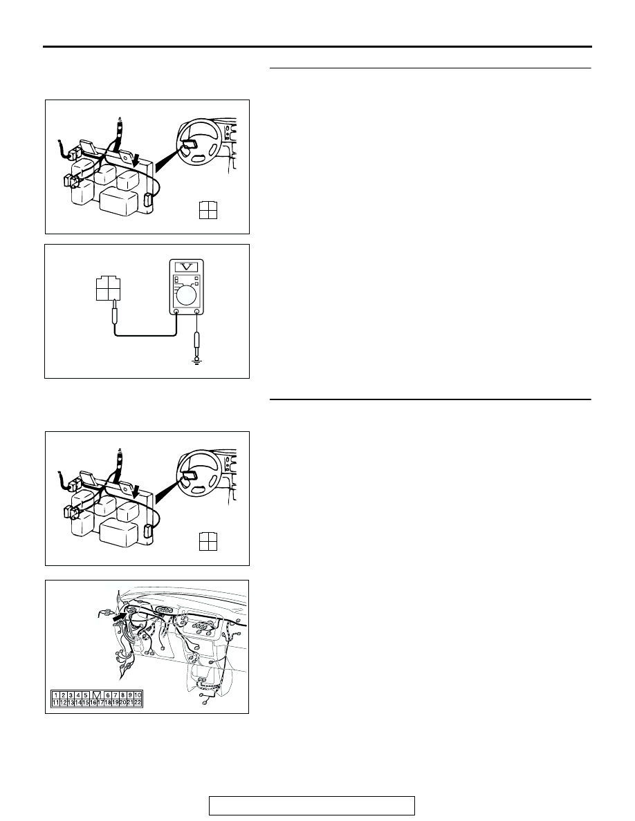
STEP 14. Check the power window relay supply circuit 
[fusible link (10)] at power window relay connector C-75X.
(1) Remove the power window relay, and measure at power 

window relay connector C-75X (relay box side).

(2) Measure the voltage between terminal 3 and ground.
Q: Is the measured voltage approximately 12 volts (battery 

positive voltage)?
YES : 
Go to Step 16.
NO :  Go to Step 15.

STEP 15. Check the harness wire between fusible link (10) 
and power window relay connector C-75X (terminal No.3).

NOTE: After inspecting intermediate connector C-41 inspect 
the wires. If intermediate connector C-41 is damaged, repair or 
replace it. Refer to GROUP 00E 

P.00E-2

, Harness Connector 

Inspection. Then go to Step 21.
Q: Is the harness wire damaged?

YES : Repair or replace the harness wire, then go to Step 

21.

NO :  Replace the power window relay and then go to Step 

21.

AC202074

4

2 1

3

CONNECTOR: C-75X

AB

C-75X

COMPONENT 

SIDE

1

2

3

4

AC005051

C-75X HARNESS CONNECTOR:
COMPONENT SIDE

AC

AC202074

4

2 1

3

CONNECTOR: C-75X

AB

C-75X

COMPONENT 

SIDE

AC309309AE

CONNECTOR: C-41

C-41

DOOR

TSB Revision

BODY

42-112

STEP 16. Check power window main switch connector 
F-05 for loose, corroded or damaged terminals, or 
terminals pushed back in the connector.
Q: Is the connectors in good condition?

YES : Go to Step 17.
NO :  Repair or replace the damaged components. Refer to 

GROUP 00E 

P.00E-2

, Harness Connector inspection. 

Then go to Step 21.

STEP 17. Check the power supply circuit [power window 
relay] at power window main switch connector F-05.
(1) Disconnect power window main switch connector F-05, and 

measure at the harness side.

(2) Turn the ignition switch to "ON" position.

(3) Measure the voltage between terminal 13 and ground.

• The measured value should be approximately 12 volts 

(battery positive voltage).

Q: Does the measured voltage correspond with this range?

YES : Go to Step 19.
NO :  Go to Step 18.

AC202003

1

7

2

8

10

11

5

13

6

14

12

4

9

3

CONNECTOR: F-05

AB

COMPONENT SIDE

FRONT  
DOOR (LH)

F-05

AC202003

1

7

2

8

10

11

5

13

6

14

12

4

9

3

CONNECTOR: F-05

AB

COMPONENT SIDE

FRONT  
DOOR (LH)

F-05

5 4

6

13

3 2 1

14

12 1110 9

8 7

AC005056AC

F-05 HARNESS CONNECTOR:
COMPONENT SIDE

DOOR

TSB Revision

BODY

42-113

STEP 18. Check the harness wire between power window 
relay connector C-75X (terminal No.1) and power window 
main switch connector F-05 (terminal No.13).

NOTE: After inspecting intermediate connector C-40 inspect 
the wires. If intermediate connector C-40 is damaged, repair or 
replace it. Refer to GROUP 00E 

P.00E-2

, Harness Connector 

Inspection. Then go to Step 21.
Q: Is the harness wire damaged?

YES : Repair or replace the harness wire, then go to Step 

21.

NO :  Replace the power window main switch and then go 

to Step 21.

AC202074

4

2 1

3

CONNECTOR: C-75X

AB

C-75X

COMPONENT 

SIDE

AC202003

1

7

2

8

10

11

5

13

6

14

12

4

9

3

CONNECTOR: F-05

AB

COMPONENT SIDE

FRONT  
DOOR (LH)

F-05

AC309309AF

C-40

CONNECTOR: C-40

DOOR

TSB Revision

BODY

42-114

STEP 19. Measure the power window main switch ground 
circuit at power window main switch connector F-05.
(1) Disconnect power window main switch connector F-05, and 

measure at the harness side.

(2) Measure the resistance between terminal 12 and ground.
Q: Is the measured resistance less than 2 ohms?

YES : Go to Step 21.
NO :  Go to Step 20.

STEP 20. Check the harness wire between power window 
main switch connector F-05 (terminal No.12) and ground.

NOTE: After inspecting intermediate connector C-40 inspect 
the wires. If intermediate connector C-40 is damaged, repair or 
replace it. Refer to GROUP 00E 

P.00E-2

, Harness Connector 

Inspection. Then go to Step 21.
Q: Is the harness wire damaged?

YES : Repair or replace the harness wire, then go to Step 

21.

NO :  Replace the power window main switch and then go 

to Step 21.

AC202003

1

7

2

8

10

11

5

13

6

14

12

4

9

3

CONNECTOR: F-05

AB

COMPONENT SIDE

FRONT  
DOOR (LH)

F-05

5 4

6

13

3 2 1

14

12 1110 9

8 7

AC005057

F-05 HARNESS CONNECTOR:
COMPONENT SIDE

AC

AC202003

1

7

2

8

10

11

5

13

6

14

12

4

9

3

CONNECTOR: F-05

AB

COMPONENT SIDE

FRONT  
DOOR (LH)

F-05

AC309309AF

C-40

CONNECTOR: C-40


Content   ..  462  463  464  465   ..