Mitsubishi Montero Sport (2004+). Manual - part 465


  Index      Mitsubishi     Mitsubishi Montero Sport - service repair manual 2004 year


Search            


Content   ..  463  464  465  466   ..


Mitsubishi Montero Sport (2004+). Manual - part 465


DOOR

TSB Revision

BODY

42-115

STEP 21. Retest the system.
Q: Does the power window function operate normally?

YES : The procedure is complete.
NO :  Return to Step 1.

INSPECTION PROCEDURE 3: Power Window Timer Function does not Work Normally. (Power 
Window Operates) <Vehicles with keyless entry system>

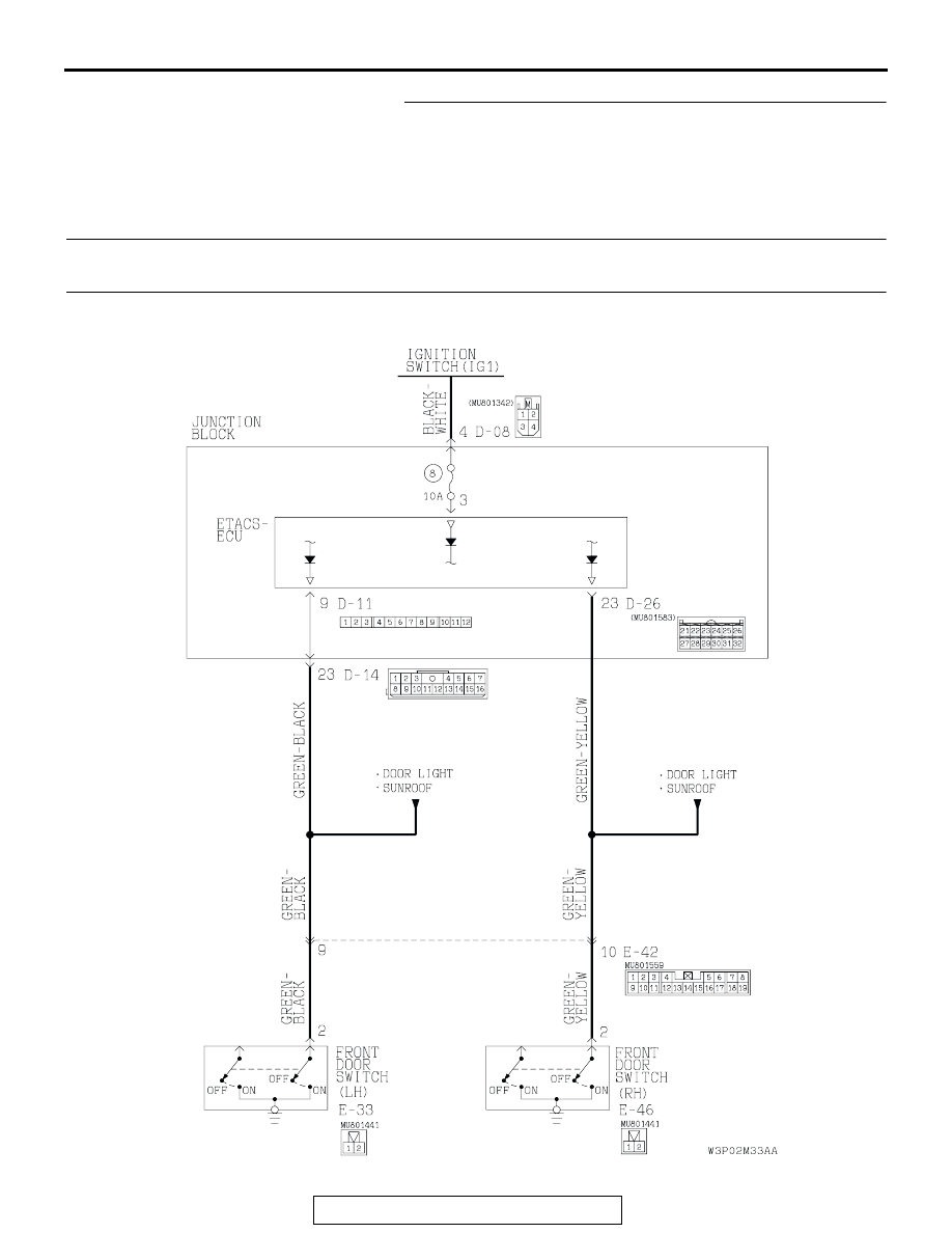
Front Door Switch Circuit

DOOR

TSB Revision

BODY

42-116

.

TECHNICAL DESCRIPTION (COMMENT)
The ETACS-ECU operates the power window timer 
function, based on input signals from the following 
switches:

• Ignition switch (IG1)

• Driver's or front passenger's door switch

If the power window timer function do not work nor-
mally, the input signal circuit or the ETACS-ECU may 
be defective.

.

TROUBLESHOOTING HINTS

• Malfunction of the front door switch

• Malfunction of the ignition switch

• Malfunction of the ETACS-ECU

• Damaged harness wires or connectors

DIAGNOSIS

Required Special Tools:

• MB991223: Harness Set

• MB991529: Diagnostic Trouble Code Check Harness

• MB991958: Scan Tool (MUT-III Sub Assembly)

• MB991824: Vehicle Communication Interface (V.C.I.)

• MB991827: MUT-III USB Cable

• MB991911: MUT-III Main Harness B

STEP 1. Choose method of the ETACS-ECU input signal 
check.
Q: Is the ETACS-ECU input signal check performed by 

scan tool MB991958 or a voltmeter?
By scan tool MB991958 : 
Go to Step 2.
By a voltmeter : Go to Step 3.

AC004311

JUNCTION BLOCK(REAR)

CONNECTORS: D-08, D-11, D-14, D-26

BF

D-14 (B)

D-11

D-26 (B)

D-08

AC004329AH

E-42

E-46

E-33

CONNECTORS: E-33, E-42, E-46

DOOR

TSB Revision

BODY

42-117

STEP 2. Check the ETACS-ECU input signal from the 
ignition switch (by using the pulse check) (by using 
MB991958).
Check the ETACS-ECU input signal [front door switches and 
ignition switch (IG1)] by using scan tool MB991958.
Check the input signals from the following switches:

• Driver's door switch

• Front passenger's door switch

• ignition switch

CAUTION

To prevent damage to scan tool MB991958, always turn the 
ignition switch to the "LOCK" (OFF) position before con-
necting or disconnecting scan tool MB991958.
(1) Connect scan tool MB991958 to the data link connector.
(2) Operate scan tool MB991958 as follows:

1. Select "SYSTEM SELECT."
2. Select "SWS."
3. Select "PULSE CHECK."

(3) Open the driver’s door or front passenger’s door.
(4) Turn the ignition switch (IG1) to ''ON'' position.
(5) Check that scan tool MB991958 sounds
Q: Does the tone alarm of scan tool MB991958 sound when 

the input signal enters?
YES : 
Replace the ETACS-ECU and then go to Step 11.
NO <Driver's door switch and passenger’s door switch 
input signal> : 
Go to Step 5.
NO <Ignition switch input signal> : Go to Step 7.

STEP 3. Check the ETACS-ECU input signal from the 
driver's door switch and passenger’s door switch (by 
using a voltmeter).
(1) Use special tool MB991529 to connect a voltmeter between 

ground terminal 4 or 5 and ETACS-ECU terminal 9 of the 
data link connector.

(2) Check that the voltmeter indicator deflects once when 

driver's door switch or passenger’s door switch operated 
<open (on)/depressed (off)>.

Q: Does the voltmeter indicator deflect?

YES : Replace the ETACS-ECU and then go to Step 4.
NO :  Go to Step 5.

AK303629AB

MB991911

MB991827

MB991824 

16-PIN

7

6

5

4

3

2

1

14

13

12

11

10

9

8

16

15

AC004323

MB991529

GROUND TERMINAL

ETACS TERMINAL

AB

DOOR

TSB Revision

BODY

42-118

STEP 4. Check the input signal from the ignition switch (by 
using a voltmeter).
(1) Use special tool MB991529 to connect a voltmeter between 

ground terminal 4 or 5 and ETACS-ECU terminal 9 of the 
data link connector.

(2) Check that the voltmeter indicator deflects once when the 

ignition switch is operated <ACC - ON>.

Q: Does the voltmeter indicator deflect?

YES : Replace the ETACS-ECU and then go to Step 11.
NO :  Go to Step 7.

STEP 5. Check driver's door switch connector E-33 and 
front passenger’s door switch connector E-46 for loose, 
corroded or damaged terminals, or terminals pushed back 
in the connector.
Q: Are driver's door switch connector E-33 and front 

passenger’s door switch E-46 in good condition?
YES : 
Go to step 6.
NO :  Repair or replace the damaged components. Refer to 

GROUP 00E 

P.00E-2

, Harness Connector inspection. 

Then go to Step 11.

7

6

5

4

3

2

1

14

13

12

11

10

9

8

16

15

AC004323

MB991529

GROUND TERMINAL

ETACS TERMINAL

AB

AC004329AJ

E-46

E-33

CONNECTORS: E-33, E-46

COMPONENT SIDE

2 1


Content   ..  463  464  465  466   ..