Mitsubishi Montero (2004+). Manual - part 880
AUTOMATIC TRANSMISSION DIAGNOSIS
TSB Revision
AUTOMATIC TRANSMISSION
23A-95
TROUBLESHOOTING HINTS (THE MOST LIKELY
CAUSES FOR THIS CODE TO BE SET:)
• Malfunction of the output shaft speed sensor
• Malfunction of the output shaft
• Damaged harness, connector
• Malfunction of the PCM
DIAGNOSIS
Required Special Tool:
• MB991958: Scan Tool (MUT-III Sub Assembly)
• MB991824: V.C.I.
• MB991827: MUT-III USB Cable
• MB991911: MUT-III Main Harness B
STEP 1. Using scan tool MB991958, check data list item 23:
Output Shaft Speed Sensor.
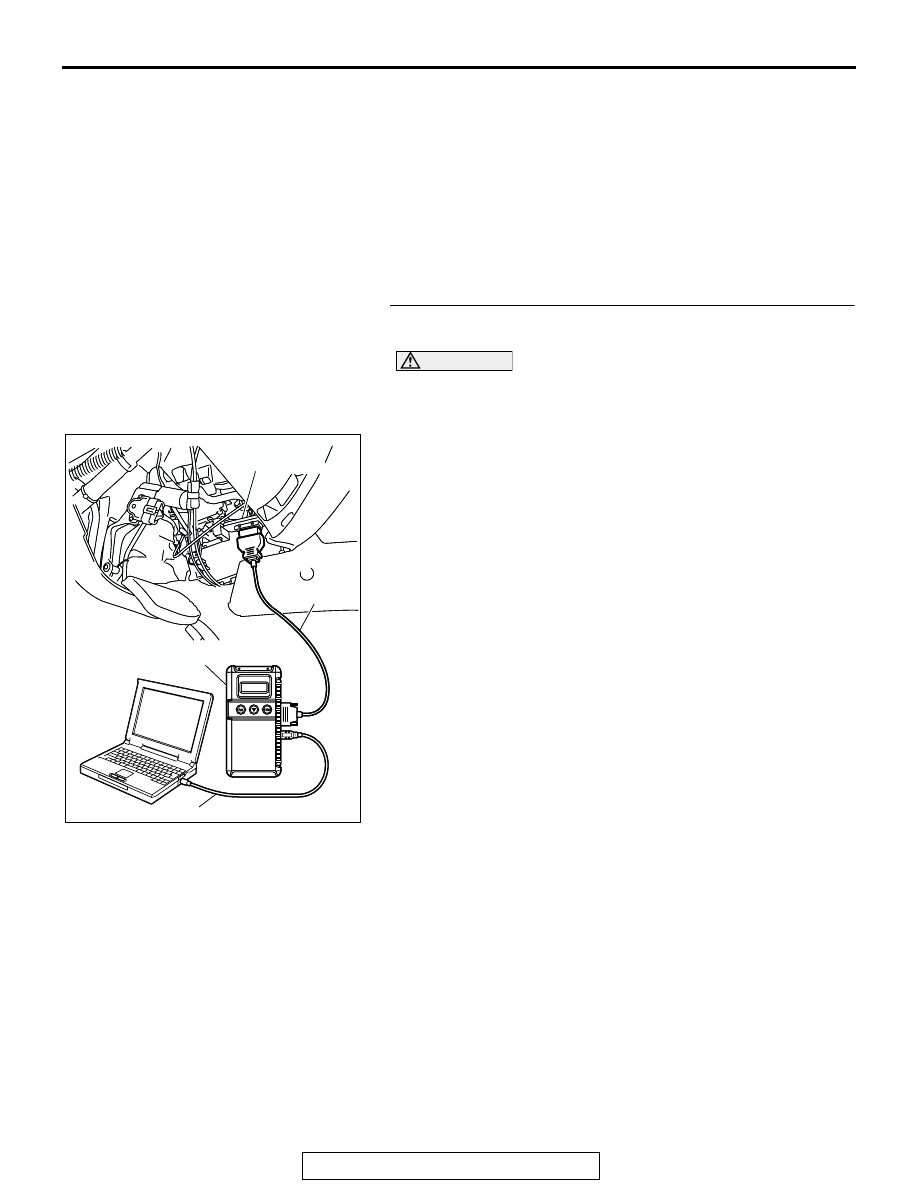
CAUTION
To prevent damage to scan tool MB991958, always turn the
ignition switch to the "LOCK" (OFF) position before con-
necting or disconnecting scan tool MB991958.
(1) Connect scan tool MB991958 to the data link connector.
(2) Start the engine.
(3) Set scan tool MB991958 to the data reading mode.
• Item 23: Output Shaft Speed Sensor.
• When driving at constant speed of 50 km/h (31
mph), the display should be "1,400
− 1,700 r/min"
(Gear range: 4th gear).
(4) Turn the ignition switch to the "LOCK" (OFF) position.
Q: Is the sensor operating properly?
YES : It can be assumed that this malfunction is intermittent.
Refer to GROUP 00, How to Use
Troubleshooting/Inspection Service Points
− How to
Cope with Intermittent Malfunction
.
NO : Go to Step 2.
AC307591 AC
MB991911
MB991824
MB991827
AC307591
DATA LINK
CONNECTOR