Mitsubishi Montero (2004+). Manual - part 585


  Index      Mitsubishi     Mitsubishi Montero - service repair manual 2004 year


Search            


Content   ..  583  584  585  586   ..


Mitsubishi Montero (2004+). Manual - part 585


FRONT SEAT ASSEMBLY

TSB Revision

INTERIOR

52A-17

REMOVAL SERVICE POINT

.

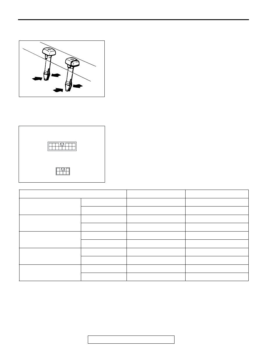
<<A>>HEAD RESTRAINT GUIDE REMOVAL

INSPECTION

M1522001400095

Power seat manual switch continuity check

ACX01300AB

1 2 3

4 5 6

7 8 9

11

10

12 1314

AC203971

1
3 4 5

2
6

POWER SEAT SWITCH CONNECTOR

LUMBAR SUPPORT SWICH CONNECTOR

AC

SWITCH POSITION

TESTER CONNECTION

SPECIFIED CONDITION

Reclining switch

FRONT

4-14, 3-13

Less than 2 ohms

REAR

4-13, 3-14

Less than 2 ohms

Slide switch

FRONT

7-14, 8-13

Less than 2 ohms

REAR

7-13, 8-14

Less than 2 ohms

Front height switch

UP

5-14, 6-13

Less than 2 ohms

DOWN

5-13, 6-14

Less than 2 ohms

Rear height switch

UP

2-14, 1-13

Less than 2 ohms

DOWN

2-13, 1-14

Less than 2 ohms

Lumbar support switch

FRONT

4-5, 3-6

Less than 2 ohms

REAR

4-6, 3-5

Less than 2 ohms

FRONT SEAT ASSEMBLY

TSB Revision

INTERIOR

52A-18

Operation check of power seat motor

1. Disconnect the connector of each motor.
2. Check that when the battery is directly connected to the 

motor terminal, the motor turns smoothly and each adjusting 
mechanism operates as stated below for each motor.

(1) Connect the battery power supply to the terminal 1 and 

ground the terminal 2 for the front height down side, rear 
slide side and the rear lumbar support side.

(2) Connect the battery power supply to the terminal 2 and 

ground the terminal 1 for the front height up side, front 
slide side and front lumbar support side.

(3) Connect the battery power supply to the terminal 3 and 

ground the terminal 4 for the rear height down side and 
connect the battery power supply to the terminal 4 and 
ground the terminal 3 for the rear height up side.

(4) Connect the battery power supply to the terminal 2 and 

ground the terminal 1 for the rear reclining side and 
connect the battery power supply to the terminal 1 and 
ground the terminal 2 for the front reclining side.

3. If abnormality was found, check the power seat adjuster 

assembly.

1 2

1

2

1 2

1 2 3 4

1 2 3 4

ACX01837

AB

SAMPLE

RECLINING 
MOTOR 
CONNECTOR

SLIDEMOTOR 
CONNECTOR

LUMBAR
SUPPORT 
MOTOR 
CONNECTOR

FRONT HEIGHT
MOTOR 
CONNECTOR

REAR HEIGHT 
MOTOR 
CONNECTOR

REAR SEAT ASSEMBLY

TSB Revision

INTERIOR

52A-19

REAR SEAT ASSEMBLY

REMOVAL AND INSTALLATION

M1522001800327

CLAW POSITIONS 

AC006064AB

2

1

1

1

3

2

44 ± 10 N·m
33 ± 7 ft-lb

44 ± 10 N·m
33 ± 7 ft-lb

1. HEAD RESTRAINT

REMOVAL STEPS

2. SEAT ANCHOR COVER
3. SECOND SEAT ASSEMBLY

AC101440

<SEAT ANCHOR COVER>

A

A

B

B

A

A

SECTION A - A

SECTION B - B

SEAT ANCHOR
COVER

CLAW

SECOND SEAT
ASSEMBLY

SEAT HINGE COVER

CLAW

SEAT SIDE BACK
ASSEMBLY

AB

NOTE
         :Claw position

REAR SEAT ASSEMBLY

TSB Revision

INTERIOR

52A-20

DISASSEMBLY AND ASSEMBLY

M1522002000249

<LH SIDE>

ACX00629

13 ± 2 N·m

AF

28

28

29

29

30

30

38

38

12 ± 2 N·m
107 ± 17 in-lb

44 ± 10 N·m
33 ± 7 ft-lb

44 ± 10 N·m
33 ± 7 ft-lb

44 ± 10 N·m
33 ± 7 ft-lb

39

39

40

26

4

44 ± 10 N·m
33 ± 7 ft-lb

32

7

36

37

35

5

31

6

34

9

22

8

25

27

10

14

3

12 ± 2 N·m
107 ± 17 in-lb

21

52 ± 7 N·m
38 ± 5 ft-lb

44 ± 10 N·m
33 ± 7 ft-lb

1

2

11

15

16

13

12

18

19

20

23

24

115 ± 18 in-lb

17

N

33

N


Content   ..  583  584  585  586   ..