Mitsubishi Montero (2004+). Manual - part 506


  Index      Mitsubishi     Mitsubishi Montero - service repair manual 2004 year


Search            


Content   ..  504  505  506  507   ..


Mitsubishi Montero (2004+). Manual - part 506


TIRE PRESSURE MONITORING SYSTEM (TPMS)

TSB Revision

WHEEL AND TIRE

31-95

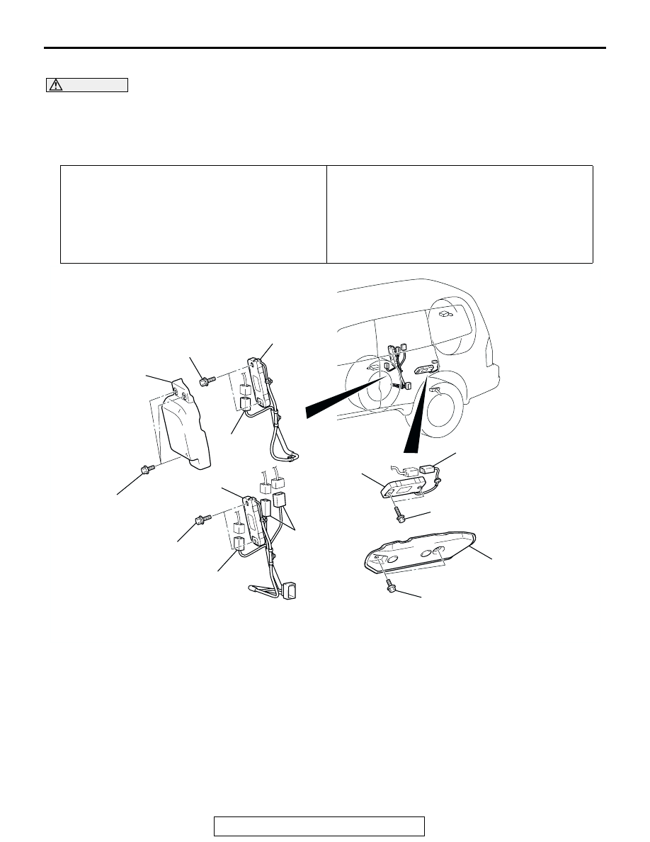
<TPMS ANTENNA (REAR)>

CAUTION

• Do not drop the TPMS antenna.
• TPMS antenna should not be exposed to temperatures above 105°C (221°F).
• If any TPMS antenna is replaced, execute "Tire Pressure Sensor ID Registration" on scan tool 

MB991958 "Special Function" to check the receiver function. 

Pre-removal Operation
• Upper Quarter Trim and Lower Quarter Trim Removal 

(Refer to GROUP 52A, Trims 

P.52A-8

).

Post-installation Operation
• Lower Quarter Trim and Upper Quarter Trim Installation 

(Refer to GROUP 52A, Trims 

P.52A-8

).

• Receiver Function Check by Executing "Tire Pressure 

Sensor ID Registration" <If a new TPMS antenna is 

installed> (Refer to 

P.31-89

).

• TPMS Failure Check (check that the TPMS warning light 

does not illuminate or flash).

AC307578 AB

<REAR-RH (VEHICLES WITH REAR A/C, 
REAR COOLER OR REAR HEATER)>

8.8 ± 2.0 N·m
78 ± 17 in-lb

8.8 ± 2.0 N·m
78 ± 17 in-lb

8.8 ± 2.0 N·m
78 ± 17 in-lb

8.8 ± 2.0 N·m
78 ± 17 in-lb

8.8 ± 2.0 N·m
78 ± 17 in-lb

1

2

3

1

2

3

2

2

3

<REAR-RH (VEHICLES WITHOUT REAR A/C, 
REAR COOLER OR REAR HEATER)>

<REAR-LH>

TPMS ANTENNA (REAR-LH) 
REMOVAL STEPS

1.

TPMS ANTENNA COVER

2.

CONNECTOR(S)

3.

TPMS ANTENNA (REAR-LH)

TPMS ANTENNA (REAR-RH) 
REMOVAL STEPS

REAR HEATER UNIT AND REAR 
BLOWER ASSEMBLY <VEHICLES 
WITH REAR A/C, REAR COOLER 
OR REAR HEATER> (REFER TO 
GROUP 55A, REAR HEATER 
UNIT AND REAR BLOWER 
ASSEMBLY 

P.55A-134

).

1.

TPMS ANTENNA COVER

2.

CONNECTOR(S)

3.

TPMS ANTENNA (REAR-RH)

TIRE PRESSURE MONITORING SYSTEM (TPMS)

TSB Revision

WHEEL AND TIRE

31-96

TPMS RECEIVER

REMOVAL AND INSTALLATION

M1311003700027

CAUTION

• Do not drop the TPMS receiver.
• TPMS receiver should not be exposed to temperatures above 85°C (185°F).
• If the TPMS receiver is replaced, execute "Tire Pressure Sensor ID Registration" on scan tool 

MB991958 "Special Function." 

Pre-removal Operation
• Upper Quarter Trim (RH) and Lower Quarter Trim (RH) 

Removal (Refer to GROUP 52A, Trims 

P.52A-8

).

• Rear Blower Assembly Removal <Vehicles with rear A/C, 

rear cooler or rear heater> (Refer to GROUP 55A, Rear 

heater Unit and Rear Blower Assembly 

P.55A-134

).

Post-installation Operation
• Rear Blower Assembly Installation <Vehicles with rear 

A/C, rear cooler or rear heater> (Refer to GROUP 55A, 

Rear heater Unit and Rear Blower Assembly 

P.55A-134

).

• Lower Quarter Trim (RH) and Upper Quarter Trim (RH) 

Installation (Refer to GROUP 52A, Trims 

P.52A-8

).

• Tire Pressure Sensor ID Registration <If a new TPMS 

receiver is installed> (Refer to 

P.31-89

).

• TPMS Failure Check (check that the TPMS warning light 

does not illuminate or flash). 

AC307579

AC307575

AB

TPMS RECEIVER

INNER QUARTER PANEL (RH)

TIRE PRESSURE MONITORING SYSTEM (TPMS)

TSB Revision

WHEEL AND TIRE

31-97

TPMS TRANSMITTER

REMOVAL AND INSTALLATION

M1311003800024

CAUTION

• Ensure valve cap is always in place except when adjusting tire pressure.
• If the valve core and valve cap are replaced, use a genuine replacement part. The valve core is 

similar to a conventional one, but uses nickel plating to avoid corrosion.

• Relieve tire pressure by removing the valve nut rather than by removing the valve core.
• Replace the valve stem grommet with a new one every five years or when the tire is replaced.
• If you shake the TPMS transmitter, you can hear a rattle, but this is not a failure. It is normal.
• Do not drop the TPMS transmitter from height greater than 1 meter (3.3 feet).
• Do not expose the TPMS transmitter to extraneous magnetic fields.
• TPMS transmitter should not be stored at temperatures above 80°C (176°F).
• TPMS transmitter should not be exposed to temperatures above 100°C (212°F).
• If the TPMS transmitter is replaced, execute "Tire Pressure Sensor ID Registration" on scan tool 

MB991958 "Special Function." 

Pre-removal Operation
• Wheel and Tire Removal (Refer to 

P.31-93

).

Post-installation Operation
• Wheel and Tire Installation (Refer to 

P.31-93

).

• Tire Pressure Sensor ID Registration <If a new TPMS 

transmitter is installed> (Refer to 

P.31-89

).

• TPMS Failure Check (check that the TPMS warning light 

does not illuminate or flash).

AC307580 AB

1

2

3

4

N

0.25 N·m
2.5 in-lb

5.5 ± 0.5 N·m
49 ± 4 in-lb

REMOVAL STEPS

<<A>>

1.

VALVE CAP

<<A>>

2.

VALVE NUT

LET TPMS TRANSMITTER FALL 
INTO TIRE

<<B>>

TIRE BEAD

<<B>>

3.

TPMS TRANSMITTER

<<C>>

4.

GROMMET

INSTALLATION STEPS

>>A<<

4.

GROMMET

>>A<<

3.

TPMS TRANSMITTER

>>A<<

2.

VALVE NUT

>>B<<

TIRE BEAD MOUNTING

>>C<<

TIRE PRESSURE INFLATION

>>C<<

VALVE NUT RETIGHTENING

1.

VALVE CAP

TIRE PRESSURE MONITORING SYSTEM (TPMS)

TSB Revision

WHEEL AND TIRE

31-98

REMOVAL SERVICE POINTS

.

<<A>> VALVE CAP/VALVE NUT REMOVAL

CAUTION

Ensure valve cap is always in place except when adjusting 
tire pressure.
1. Remove the valve cap.
2. Rotate tire so that valve stem is in the 6 o’clock position.
3. Use a long-reach 17.2 mm (0.68 inch) socket to unscrew the 

valve nut a few turns. Slowly push valve stem into tire so 
that tire pressure is relieved.

4. Once tire pressure is relieved, remove the valve nut.

.

<<B>> TIRE BEAD/TPMS TRANSMITTER REMOVAL
1. Place on tire changing machine and break both tire beads 

ensuring that the TPMS transmitter remains in the bottom of 
the tire.

CAUTION

Be careful not to damage the TPMS transmitter.
2. Lubricate tire well and remove outer side of the tire.
3. Reach inside the tire and remove the TPMS transmitter.
4. Remove tire from rim using proper tire changing equipment 

procedures.

.

<<C>> GROMMET REMOVAL

CAUTION

Use a soft tool to remove the grommet to prevent scratch-
ing the valve of the TPMS transmitter.
Remove the grommet from the TPMS transmitter.

INSTALLATION SERVICE POINTS

.

>>A<< GROMMET/TPMS TRANSMITTER/VALVE NUT 
INSTALLATION
1. Slide inner tire bead over rim face. Use lubricant, as normal 

procedures require.

2. Install a new grommet to the TPMS transmitter.

AC307582 AB

TPMS 
TRANSMITTER

AC205765AB

TIRE

WHEEL RIM


Content   ..  504  505  506  507   ..