Mitsubishi Montero (2004+). Manual - part 507


  Index      Mitsubishi     Mitsubishi Montero - service repair manual 2004 year


Search            


Content   ..  505  506  507  508   ..


Mitsubishi Montero (2004+). Manual - part 507


TIRE PRESSURE MONITORING SYSTEM (TPMS)

TSB Revision

WHEEL AND TIRE

31-99

CAUTION

• Visually check that TPMS transmitter is not deformed 

or damaged.

• When installing the TPMS transmitter, be sure the rim, 

grommet and valve nut are clean.

• Ensure that the grommet is located inside the valve 

hole before installing the valve nut.

• While installing the valve nut, hold the valve and grom-

met firmly in contact with the rim.

• While installing the valve nut, ensure that the tool is 

kept aligned to the valve and the valve hole.

• After installing the valve nut, check that the grommet is 

compressed.

3. Mount TPMS transmitter valve through rim hole as 

illustrated. Both holes in the transmitter case should face 
away from center of rim. Tighten valve nut finger tight, then 
slowly torque the valve nut to 5.5 

± 0.5 N⋅m (49 ± 4 inch 

pounds).

CAUTION

Install the TPMS transmitter correctly. If the TPMS trans-
mitter is installed incorrectly, it may not work correctly, or 
become damaged when the tire is installed.
4. Check that the TPMS transmitter is correctly assembled 

(Refer to illustration).

• One side of lower lip of the TPMS transmitter case can 

touch the rim after torquing.

• Except for the grommet, valve nut and lower lip of the 

TPMS transmitter, no other part of the front of the TPMS 
transmitter case should be touching the rim.

.

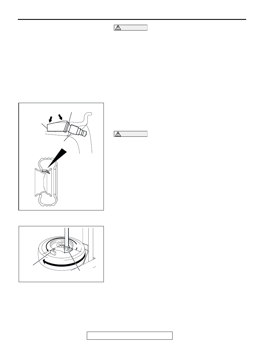
>>B<< TIRE BEAD MOUNTING
1. Place wheel and tire on turntable of tire mounting machine. 

Ensure that the TPMS transmitter is 270 degrees (3 o’clock 
position) from mounting head when the outer tire bead is 
mounted as illustrated.

2. Lubricate tire well and mount outer tire bead as normal. 

Ensure that the tire does not rotate during mounting.

.

AC205463

AC205766

AC206993AB

TPMS 
TRANSMITTER

GROMMET

VALVE NUT

HOLES

AC307581AB

TPMS 
TRANSMITTER

MOUNTING HEAD

270˚

TIRE PRESSURE MONITORING SYSTEM (TPMS)

TSB Revision

WHEEL AND TIRE

31-100

>>C<< TIRE PRESSURE INFLATION/VALVE NUT 
RETIGHTENING

CAUTION

After tire inflation, retighten the valve nut 5.5 

± 0.5 Nm (49 

± 4 inch pounds). This is necessary, because the TPMS 

transmitter is secured to the wheel with the valve nut and 
rubber grommet. The rubber grommet will be depressed 
by tire pressure or deteriorate over a period of time, which 
requires the valve nut to be retightened.
Inflate tire to required pressure, then retorque the valve nut to 
5.5 

± 0.5 N⋅m (49 ± 4 inch pounds).

SPECIFICATIONS

TSB Revision

WHEEL AND TIRE

31-101

SPECIFICATIONS

FASTENER TIGHTENING SPECIFICATION

M1311001600303

GENERAL SPECIFICATIONS

M1311000200335

NOTE: PCD (Pitch Circle Diameter) indicates the pitch circle diameter of the wheel installation holes.

SERVICE SPECIFICATIONS

M1311000300417

ITEM

SPECIFICATION

Spare wheel mounting bolt (lock cylinder)

46 

± 8 N⋅m (34 ± 5 ft-lb)

TPMS antenna cover mounting bolt

8.8 

± 2.0 N⋅m (78 ± 17 in-lb)

TPMS antenna mounting bolt

8.8 

± 2.0 N⋅m (78 ± 17 in-lb)

Valve core

0.25 N

⋅m (2.5 in-lb)

Valve nut (TPMS transmitter mounting nut)

5.5 

± 0.5 N⋅m (49 ± 4 in-lb) <when installing the 

TPMS transmitter to the wheel>
5.5 

± 0.5 N⋅m (49 ± 4 in-lb) <when retightening after 

tire inflation>

Wheel nut

108 

± 10 N⋅m (80 ± 7 ft-lb)

ITEM

SPECIFICATION

Tire Pressure Monitoring System (TPMS)

Equipped (for road tires and spare 
tire)

TPMS transmitter’s transmission frequency MHz

315

TPMS warning pressure kPa 
(psi)

Warning ON

158 (23) or less

Warning OFF

174 (25) or more

Wheel

Type

Aluminum type with TPMS 
transmitter
(exclusive wheel for TPMS)

Size

16 

× 7JJ

Amount of wheel offset mm (in)

46 (1.8)

Pitch circle diameter (PCD) mm (in)

139.7 (5.50)

Tire

Size

265/70R16 112S

ITEM

LIMIT

Tread depth of tire mm (in)

Minimum 1.6 (0.06) 

Wheel runout

Radial runout mm (in)

Maximum 1.0 (0.04)

Lateral runout mm (in)

Maximum 1.0 (0.04)

NOTES


Content   ..  505  506  507  508   ..