Mitsubishi Montero (2004+). Manual - part 1140


  Index      Mitsubishi     Mitsubishi Montero - service repair manual 2004 year


Search            


Content   ..  1138  1139  1140  1141   ..


Mitsubishi Montero (2004+). Manual - part 1140


STABILIZER BAR

TSB Revision

REAR SUSPENSION

34-19

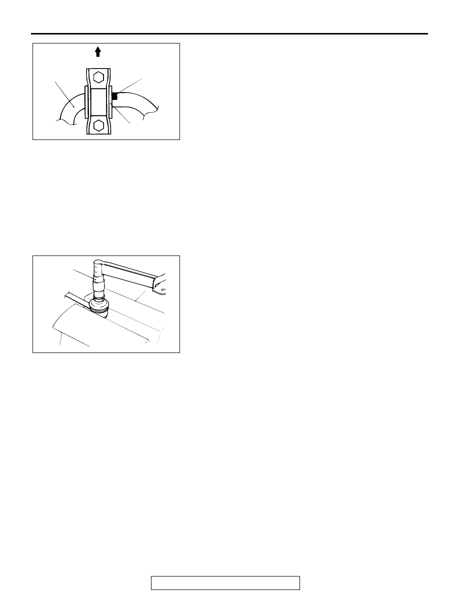
3.  Before tightening the mounting bolts, align the end of the 

identification mark with the end of the bushing.

INSPECTION

M1341015500089

• Check the bushing for wear and deterioration.

• Check the stabilizer bar for deterioration or damage. 

• Check all bolts for condition and straightness.

STABILIZER LINK BALL JOINT TURNING 
TORQUE CHECK

Required Special Tool:

• MB990326: Preload Socket

1. After shaking the ball joint stud several times, install the nut 

to the stud and use special tool MB990326 to measure the 
turning torque of the ball joint.

Standard value: 0.5 

 2.0 Nm (4  17 in-lb)

2. If the measured value exceeds the standard value, replace 

the stabilizer link.

3. If the measured value is lower than the standard value, 

check that the ball joint turns smoothly without excessive 
play. If so, it is possible to use that ball joint.

STABILIZER LINK BALL JOINT DUST COVER 
CHECK

1. Press the dust cover with your finger to check that there are 

no cracks or damage in the dust cover.

2. If the dust cover is cracked or damaged, replace the 

stabilizer link.
NOTE: If the dust cover is cracked or damaged, it is possible 
that there may also be damage to the ball joint. If it is dam-
aged during service work, replace the dust cover.

STABILIZER LINK BALL JOINT DUST COVER 
REPLACEMENT

M1341010900112

If the dust cover is damaged accidentally during service work, 
replace the dust cover as follows:

ACX00745

STABILIZER 
BAR

FRONT

IDENTIFICATION 
MARK

BUSHING

AB

AC001129

MB990326

AB

TOE CONTROL ARM ASSEMBLY AND TOE CONTROL TOWER BAR

TSB Revision

REAR SUSPENSION

34-20

1. Remove the clip ring, and then remove the dust cover.
2. Apply multipurpose grease to the inside of the dust cover.
3. Wrap plastic tape around the stabilizer link stud, and then 

install the dust cover to the stabilizer link. 

4. Secure the dust cover in place with the clip ring.
5. Press the dust cover with your finger to check that there are 

no cracks or damage in the dust cover.

TOE CONTROL ARM ASSEMBLY AND TOE CONTROL 

TOWER BAR

REMOVAL AND INSTALLATION

M1341014500053

CAUTION

*: Indicates parts which should be temporarily tightened, and then fully tightened with the vehicle on 
the ground in an unladen condition.

ACX00732AB

CLIP RING

Post-installation Operation
• Check the dust cover for cracks or damage by pushing it 

with your finger. 

• Wheel alignment check and adjustment (Refer to 

P.34-6

.)

ACX00746

67 

± 7 N

·

m

50 

± 5 ft-lb

123 

± 15 N

·

m *

91 

± 11 ft-lb *

46 

± 8 N

·

m

34 

± 6 ft-lb

3

5

1

5

2

4

AB

TOE CONTROL ARM ASSEMBLY AND TOE CONTROL TOWER BAR

TSB Revision

REAR SUSPENSION

34-21

Required Special Tool:

• MB991897: Ball Joint Remover

REMOVAL SERVICE POINTS

.

<<A>> TOE CONTROL ARM BALL JOINT AND KNUCKLE 
DISCONNECTION

CAUTION

• Do not remove the nut from ball joint. Loosen it and use 

special tool MB991897 to avoid possible damage to ball 
joint threads.

• Hang special tool MB991897 with a cord to prevent it 

from falling. 

1. Install special tool MB991897 as shown in the figure.

2. Turn the bolt and knob as necessary to make the jaws of 

special tool MB991897 parallel, tighten the bolt by hand and 
confirm that the jaws are still parallel.
NOTE: When adjusting the jaws in parallel, make sure the 
knob is in the position shown in the figure.

3. Tighten the bolt with a wrench to disconnect the ball joint.

.

REMOVAL STEPS

1. PARKING BRAKE CABLE 

MOUNTING BOLT

2. TOE CONTROL TOWER BAR

<<A>>

3. TOE CONTROL ARM BALL JOINT 

AND KNUCKLE CONNECTION

<<B>>

4. BOLT ASSEMBLY (FOR TOE 

ADJUSTING)

5. TOE CONTROL ARM ASSEMBLY

REMOVAL STEPS (Continued)

AC106820 AB

CORD

BOLT

MB991897

NUT

BALL JOINT

AC106821

KNOB

PARALLEL

BOLT

GOOD

BAD

AB

TOE CONTROL ARM ASSEMBLY AND TOE CONTROL TOWER BAR

TSB Revision

REAR SUSPENSION

34-22

<<B>> BOLT ASSEMBLY (TOE ADJUSTING BOLT) 
REMOVAL
Make mating marks on the bracket and the toe adjusting bolt, 
and then remove the toe adjusting bolt.

INSPECTION

M1341015500090

• Check the bushing for wear and deterioration.

• Check the toe control arm for bending or breakage.

• Check all bolts for condition and straightness.

.

TOE CONTROL ARM BALL JOINT TURNING TORQUE 
CHECK

Required Special Tool:

• MB990326: Preload Socket

1. After shaking the ball joint stud several times, install the nut 

to the stud and use special tool MB990326 to measure the 
turning torque of the ball joint.

Standard value: 0.7 

 1.0 Nm (6  9 in-lb)

2. If the measured value exceeds the standard value, replace 

the toe control arm ball joint assembly.

3. If the measured value is lower than the standard value, 

check that the toe control arm ball joint turns smoothly 
without excessive play. If so, it is possible to use that ball 
joint.

.

TOE CONTROL ARM BALL JOINT DUST COVER CHECK
1. Press the dust cover with your finger to check that there are 

no cracks or damage in the dust cover.

2. If the dust cover is cracked or damaged, replace the toe 

control arm ball joint assembly.
NOTE: If the dust cover is cracked or damaged, it is possible 
that there may also be damage to the ball joint. If it is dam-
aged during service work, replace the dust cover.

TOE CONTROL ARM BALL JOINT DUST COVER 
REPLACEMENT

M1341014800139

Required Special Tool:

• MB990800: Ball Joint Remover and Installer

If the dust cover is damaged accidentally during service work, 
replace the dust cover as follows:
1. Remove the clip ring, and then remove the dust cover.

ACX00733

TOE 
ADJUSTMENT 
BOLT

TOE 
CONTROL ARM

AB

ACX00716

MB990326

AB


Content   ..  1138  1139  1140  1141   ..